Disclaimer: This webpage is a modification of @karanpratapsingh’s system-design repository with CC BY-NC-ND 4.0 license. I have created this repository only for my personal learning purpose. I do not hold any right to distribute or share the content. Please contact the original creator for any permissions.
System Design Course
Learn how to design systems at scale and prepare for system design interviews.
Table of contents
-
Getting Started
-
Chapter I
-
Chapter II
-
Chapter III
- N-tier architecture
- Message Brokers
- Message Queues
- Publish-Subscribe
- Enterprise Service Bus (ESB)
- Monoliths and Microservices
- Event-Driven Architecture (EDA)
- Event Sourcing
- Command and Query Responsibility Segregation (CQRS)
- API Gateway
- REST, GraphQL, gRPC
- Long polling, WebSockets, Server-Sent Events (SSE)
-
Chapter IV
-
Chapter V
-
Appendix
What is system design?
Before we start this course, let’s talk about what even is system design.
System design is the process of defining the architecture, interfaces, and data for a system that satisfies specific requirements. System design meets the needs of your business or organization through coherent and efficient systems. It requires a systematic approach to building and engineering systems. A good system design requires us to think about everything, from infrastructure all the way down to the data and how it’s stored.
Why is System Design so important?
System design helps us define a solution that meets the business requirements. It is one of the earliest decisions we can make when building a system. Often it is essential to think from a high level as these decisions are very difficult to correct later. It also makes it easier to reason about and manage architectural changes as the system evolves.
IP
An IP address is a unique address that identifies a device on the internet or a local network. IP stands for “Internet Protocol”, which is the set of rules governing the format of data sent via the internet or local network.
In essence, IP addresses are the identifier that allows information to be sent between devices on a network. They contain location information and make devices accessible for communication. The internet needs a way to differentiate between different computers, routers, and websites. IP addresses provide a way of doing so and form an essential part of how the internet works.
Versions
Now, let’s learn about the different versions of IP addresses:
IPv4
The original Internet Protocol is IPv4 which uses a 32-bit numeric dot-decimal notation that only allows for around 4 billion IP addresses. Initially, it was more than enough but as internet adoption grew we needed something better.
Example: 102.22.192.181
IPv6
IPv6 is a new protocol that was introduced in 1998. Deployment commenced in the mid-2000s and since the internet users have grown exponentially, it is still ongoing.
This new protocol uses 128-bit alphanumeric hexadecimal notation. This means that IPv6 can provide about ~340e+36 IP addresses. That’s more than enough to meet the growing demand for years to come.
Example: 2001:0db8:85a3:0000:0000:8a2e:0370:7334
Types
Let’s discuss types of IP addresses:
Public
A public IP address is an address where one primary address is associated with your whole network. In this type of IP address, each of the connected devices has the same IP address.
Example: IP address provided to your router by the ISP.
Private
A private IP address is a unique IP number assigned to every device that connects to your internet network, which includes devices like computers, tablets, and smartphones, which are used in your household.
Example: IP addresses generated by your home router for your devices.
Static
A static IP address does not change and is one that was manually created, as opposed to having been assigned. These addresses are usually more expensive but are more reliable.
Example: They are usually used for important things like reliable geo-location services, remote access, server hosting, etc.
Dynamic
A dynamic IP address changes from time to time and is not always the same. It has been assigned by a Dynamic Host Configuration Protocol (DHCP) server. Dynamic IP addresses are the most common type of internet protocol addresses. They are cheaper to deploy and allow us to reuse IP addresses within a network as needed.
Example: They are more commonly used for consumer equipment and personal use.
OSI Model
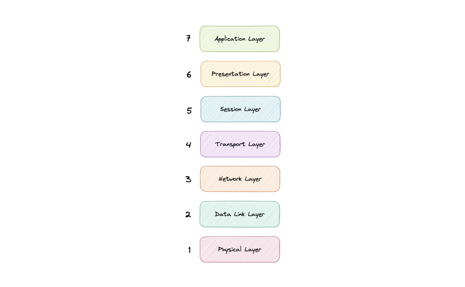
The OSI Model is a logical and conceptual model that defines network communication used by systems open to interconnection and communication with other systems. The Open System Interconnection (OSI Model) also defines a logical network and effectively describes computer packet transfer by using various layers of protocols.
The OSI Model can be seen as a universal language for computer networking. It’s based on the concept of splitting up a communication system into seven abstract layers, each one stacked upon the last.
Why does the OSI model matter?
The Open System Interconnection (OSI) model has defined the common terminology used in networking discussions and documentation. This allows us to take a very complex communications process apart and evaluate its components.
While this model is not directly implemented in the TCP/IP networks that are most common today, it can still help us do so much more, such as:
- Make troubleshooting easier and help identify threats across the entire stack.
- Encourage hardware manufacturers to create networking products that can communicate with each other over the network.
- Essential for developing a security-first mindset.
- Separate a complex function into simpler components.
Layers
The seven abstraction layers of the OSI model can be defined as follows, from top to bottom:
Application
This is the only layer that directly interacts with data from the user. Software applications like web browsers and email clients rely on the application layer to initiate communication. But it should be made clear that client software applications are not part of the application layer, rather the application layer is responsible for the protocols and data manipulation that the software relies on to present meaningful data to the user. Application layer protocols include HTTP as well as SMTP.
Presentation
The presentation layer is also called the Translation layer. The data from the application layer is extracted here and manipulated as per the required format to transmit over the network. The functions of the presentation layer are translation, encryption/decryption, and compression.
Session
This is the layer responsible for opening and closing communication between the two devices. The time between when the communication is opened and closed is known as the session. The session layer ensures that the session stays open long enough to transfer all the data being exchanged, and then promptly closes the session in order to avoid wasting resources. The session layer also synchronizes data transfer with checkpoints.
Transport
The transport layer (also known as layer 4) is responsible for end-to-end communication between the two devices. This includes taking data from the session layer and breaking it up into chunks called segments before sending it to the Network layer (layer 3). It is also responsible for reassembling the segments on the receiving device into data the session layer can consume.
Network
The network layer is responsible for facilitating data transfer between two different networks. The network layer breaks up segments from the transport layer into smaller units, called packets, on the sender’s device, and reassembles these packets on the receiving device. The network layer also finds the best physical path for the data to reach its destination this is known as routing. If the two devices communicating are on the same network, then the network layer is unnecessary.
Data Link
The data link layer is very similar to the network layer, except the data link layer facilitates data transfer between two devices on the same network. The data link layer takes packets from the network layer and breaks them into smaller pieces called frames.
Physical
This layer includes the physical equipment involved in the data transfer, such as the cables and switches. This is also the layer where the data gets converted into a bit stream, which is a string of 1s and 0s. The physical layer of both devices must also agree on a signal convention so that the 1s can be distinguished from the 0s on both devices.
TCP and UDP
TCP
Transmission Control Protocol (TCP) is connection-oriented, meaning once a connection has been established, data can be transmitted in both directions. TCP has built-in systems to check for errors and to guarantee data will be delivered in the order it was sent, making it the perfect protocol for transferring information like still images, data files, and web pages.
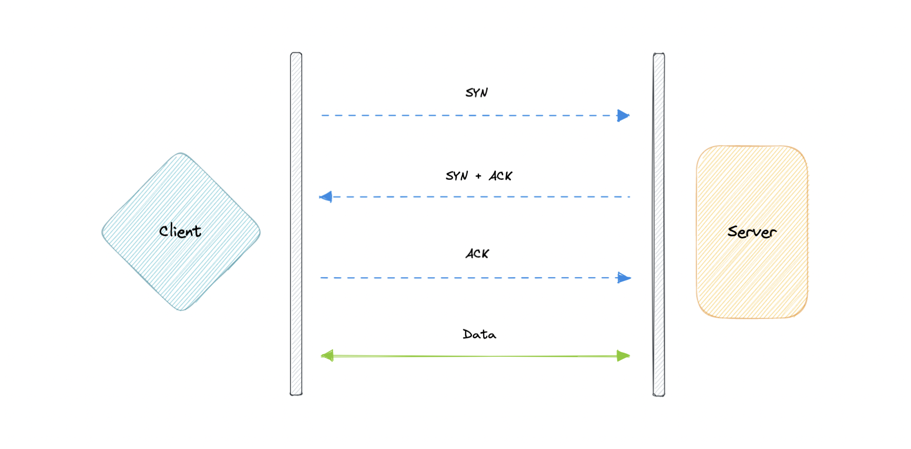
But while TCP is instinctively reliable, its feedback mechanisms also result in a larger overhead, translating to greater use of the available bandwidth on the network.
UDP
User Datagram Protocol (UDP) is a simpler, connectionless internet protocol in which error-checking and recovery services are not required. With UDP, there is no overhead for opening a connection, maintaining a connection, or terminating a connection. Data is continuously sent to the recipient, whether or not they receive it.
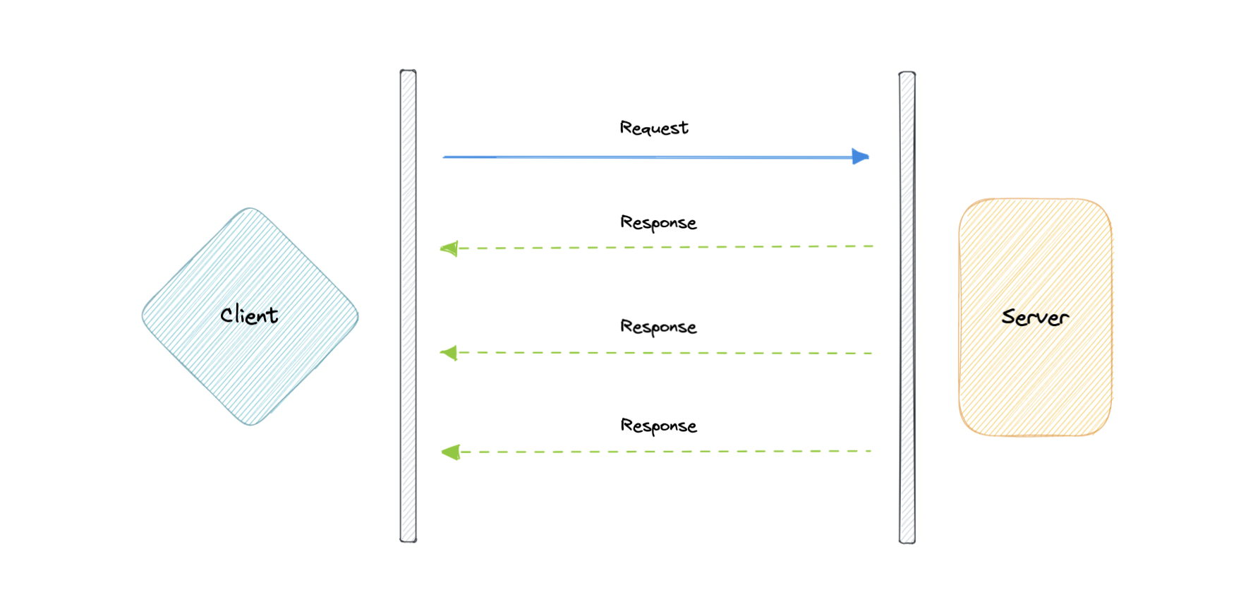
It is largely preferred for real-time communications like broadcast or multicast network transmission. We should use UDP over TCP when we need the lowest latency and late data is worse than the loss of data.
TCP vs UDP
TCP is a connection-oriented protocol, whereas UDP is a connectionless protocol. A key difference between TCP and UDP is speed, as TCP is comparatively slower than UDP. Overall, UDP is a much faster, simpler, and more efficient protocol, however, retransmission of lost data packets is only possible with TCP.
TCP provides ordered delivery of data from user to server (and vice versa), whereas UDP is not dedicated to end-to-end communications, nor does it check the readiness of the receiver.
| Feature | TCP | UDP |
|---|---|---|
| Connection | Requires an established connection | Connectionless protocol |
| Guaranteed delivery | Can guarantee delivery of data | Cannot guarantee delivery of data |
| Re-transmission | Re-transmission of lost packets is possible | No re-transmission of lost packets |
| Speed | Slower than UDP | Faster than TCP |
| Broadcasting | Does not support broadcasting | Supports broadcasting |
| Use cases | HTTPS, HTTP, SMTP, POP, FTP, etc | Video streaming, DNS, VoIP, etc |
Domain Name System (DNS)
Earlier we learned about IP addresses that enable every machine to connect with other machines. But as we know humans are more comfortable with names than numbers. It’s easier to remember a name like google.com than something like 122.250.192.232.
This brings us to Domain Name System (DNS) which is a hierarchical and decentralized naming system used for translating human-readable domain names to IP addresses.
How DNS works
Video: https://youtu.be/vhfRArT11jc
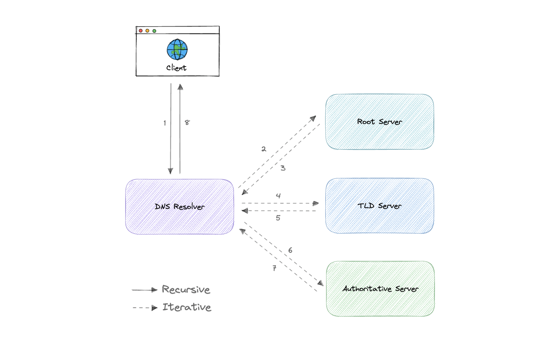
DNS lookup involves the following eight steps:
- A client types example.com into a web browser, the query travels to the internet and is received by a DNS resolver.
- The resolver then recursively queries a DNS root nameserver.
- The root server responds to the resolver with the address of a Top Level Domain (TLD).
- The resolver then makes a request to the
.comTLD. - The TLD server then responds with the IP address of the domain’s nameserver, example.com.
- Lastly, the recursive resolver sends a query to the domain’s nameserver.
- The IP address for example.com is then returned to the resolver from the nameserver.
- The DNS resolver then responds to the web browser with the IP address of the domain requested initially.
Once the IP address has been resolved, the client should be able to request content from the resolved IP address. For example, the resolved IP may return a webpage to be rendered in the browser
Server types
Now, let’s look at the four key groups of servers that make up the DNS infrastructure.
DNS Resolver
A DNS resolver (also known as a DNS recursive resolver) is the first stop in a DNS query. The recursive resolver acts as a middleman between a client and a DNS nameserver. After receiving a DNS query from a web client, a recursive resolver will either respond with cached data, or send a request to a root nameserver, followed by another request to a TLD nameserver, and then one last request to an authoritative nameserver. After receiving a response from the authoritative nameserver containing the requested IP address, the recursive resolver then sends a response to the client.
DNS root server
A root server accepts a recursive resolver’s query which includes a domain name, and the root nameserver responds by directing the recursive resolver to a TLD nameserver, based on the extension of that domain (.com, .net, .org, etc.). The root nameservers are overseen by a nonprofit called the Internet Corporation for Assigned Names and Numbers (ICANN).
There are 13 DNS root nameservers known to every recursive resolver. Note that while there are 13 root nameservers, that doesn’t mean that there are only 13 machines in the root nameserver system. There are 13 types of root nameservers, but there are multiple copies of each one all over the world, which use Anycast routing to provide speedy responses.
TLD nameserver
A TLD nameserver maintains information for all the domain names that share a common domain extension, such as .com, .net, or whatever comes after the last dot in a URL.
Management of TLD nameservers is handled by the Internet Assigned Numbers Authority (IANA), which is a branch of ICANN. The IANA breaks up the TLD servers into two main groups:
- Generic top-level domains: These are domains like
.com,.org,.net,.edu, and.gov. - Country code top-level domains: These include any domains that are specific to a country or state. Examples include
.uk,.us,.ru, and.jp.
Authoritative DNS server
The authoritative nameserver is usually the resolver’s last step in the journey for an IP address. The authoritative nameserver contains information specific to the domain name it serves (e.g. google.com) and it can provide a recursive resolver with the IP address of that server found in the DNS A record, or if the domain has a CNAME record (alias) it will provide the recursive resolver with an alias domain, at which point the recursive resolver will have to perform a whole new DNS lookup to procure a record from an authoritative nameserver (often an A record containing an IP address). If it cannot find the domain, returns the NXDOMAIN message.
Query Types
Video: https://youtu.be/BZISxpdl4lQ
There are three types of queries in a DNS system:
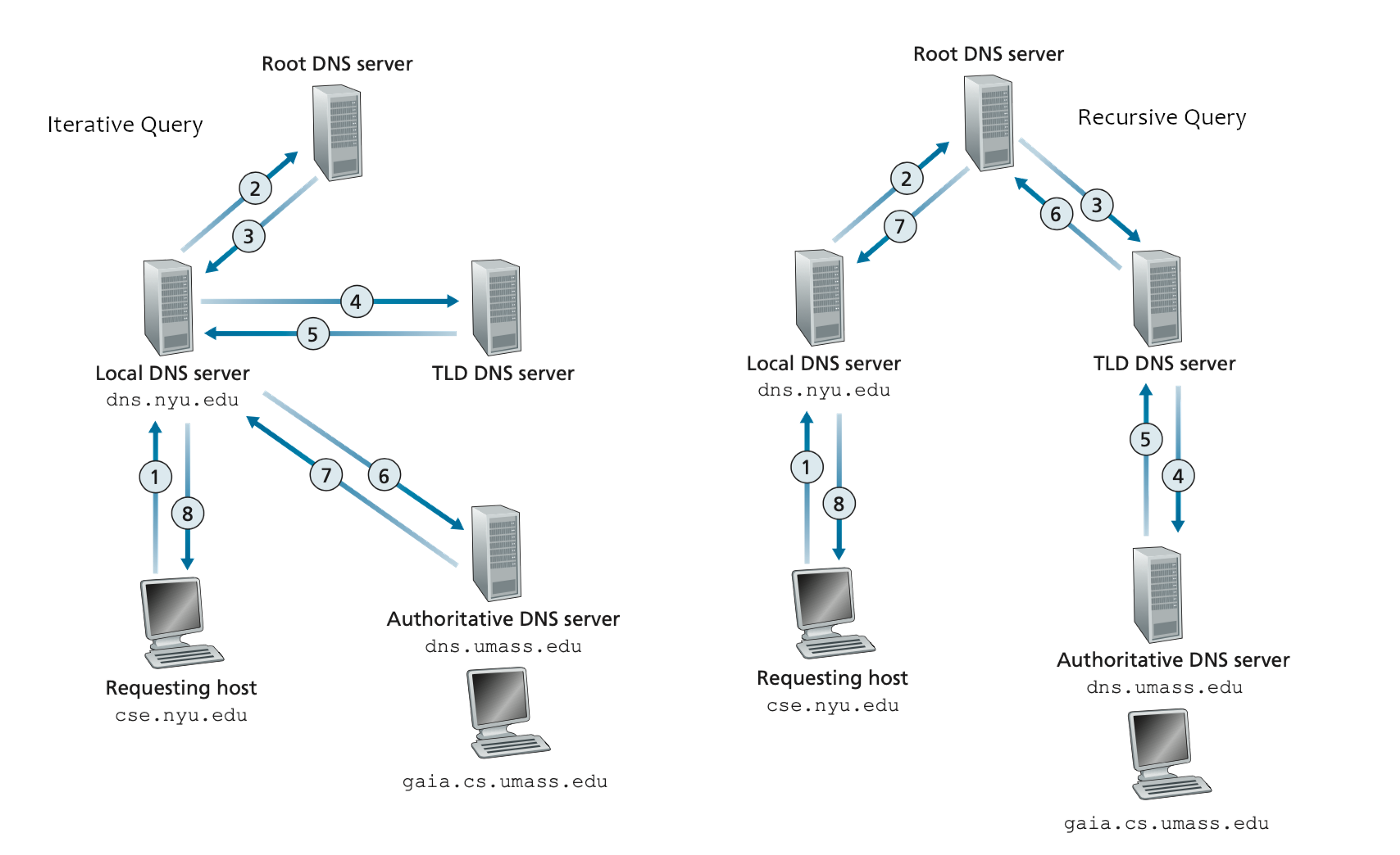
Recursive
In a recursive query, a DNS client requires that a DNS server (typically a DNS recursive resolver) will respond to the client with either the requested resource record or an error message if the resolver can’t find the record.
Iterative
In an iterative query, a DNS client provides a hostname, and the DNS Resolver returns the best answer it can. If the DNS resolver has the relevant DNS records in its cache, it returns them. If not, it refers the DNS client to the Root Server or another Authoritative Name Server that is nearest to the required DNS zone. The DNS client must then repeat the query directly against the DNS server it was referred.
Non-recursive
A non-recursive query is a query in which the DNS Resolver already knows the answer. It either immediately returns a DNS record because it already stores it in a local cache, or queries a DNS Name Server which is authoritative for the record, meaning it definitely holds the correct IP for that hostname. In both cases, there is no need for additional rounds of queries (like in recursive or iterative queries). Rather, a response is immediately returned to the client.
Records Types
DNS records (aka zone files) are instructions that live in authoritative DNS servers and provide information about a domain including what IP address is associated with that domain and how to handle requests for that domain.
These records consist of a series of text files written in what is known as DNS syntax. DNS syntax is just a string of characters used as commands that tell the DNS server what to do. All DNS records also have a “TTL”, which stands for time-to-live, and indicates how often a DNS server will refresh that record.
There are more record types but for now, let’s look at some of the most commonly used ones:
- A (Address record): This is the record that holds the IP address of a domain.
- AAAA (IP Version 6 Address record): The record that contains the IPv6 address for a domain (as opposed to A records, which stores the IPv4 address).
- CNAME (Canonical Name record): Forwards one domain or subdomain to another domain, does NOT provide an IP address.
- MX (Mail exchanger record): Directs mail to an email server.
- TXT (Text Record): This record lets an admin store text notes in the record. These records are often used for email security.
- NS (Name Server records): Stores the name server for a DNS entry.
- SOA (Start of Authority): Stores admin information about a domain.
- SRV (Service Location record): Specifies a port for specific services.
- PTR (Reverse-lookup Pointer records): Provides a domain name in reverse lookups.
- CERT (Certificate record): Stores public key certificates.
Subdomains
A subdomain is an additional part of our main domain name. It is commonly used to logically separate a website into sections. We can create multiple subdomains or child domains on the main domain.
For example, blog.example.com where blog is the subdomain, example is the primary domain and .com is the top-level domain (TLD). Similar examples can be support.example.com or careers.example.com.
DNS Zones
A DNS zone is a distinct part of the domain namespace which is delegated to a legal entity like a person, organization, or company, who is responsible for maintaining the DNS zone. A DNS zone is also an administrative function, allowing for granular control of DNS components, such as authoritative name servers.
DNS Caching
A DNS cache (sometimes called a DNS resolver cache) is a temporary database, maintained by a computer’s operating system, that contains records of all the recent visits and attempted visits to websites and other internet domains. In other words, a DNS cache is just a memory of recent DNS lookups that our computer can quickly refer to when it’s trying to figure out how to load a website.
The Domain Name System implements a time-to-live (TTL) on every DNS record. TTL specifies the number of seconds the record can be cached by a DNS client or server. When the record is stored in a cache, whatever TTL value came with it gets stored as well. The server continues to update the TTL of the record stored in the cache, counting down every second. When it hits zero, the record is deleted or purged from the cache. At that point, if a query for that record is received, the DNS server has to start the resolution process.
Reverse DNS
A reverse DNS lookup is a DNS query for the domain name associated with a given IP address. This accomplishes the opposite of the more commonly used forward DNS lookup, in which the DNS system is queried to return an IP address. The process of reverse resolving an IP address uses PTR records. If the server does not have a PTR record, it cannot resolve a reverse lookup.
Reverse lookups are commonly used by email servers. Email servers check and see if an email message came from a valid server before bringing it onto their network. Many email servers will reject messages from any server that does not support reverse lookups or from a server that is highly unlikely to be legitimate.
Note: Reverse DNS lookups are not universally adopted as they are not critical to the normal function of the internet.
Examples
These are some widely used managed DNS solutions:
Load Balancing
Load balancing lets us distribute incoming network traffic across multiple resources ensuring high availability and reliability by sending requests only to resources that are online. This provides the flexibility to add or subtract resources as demand dictates.
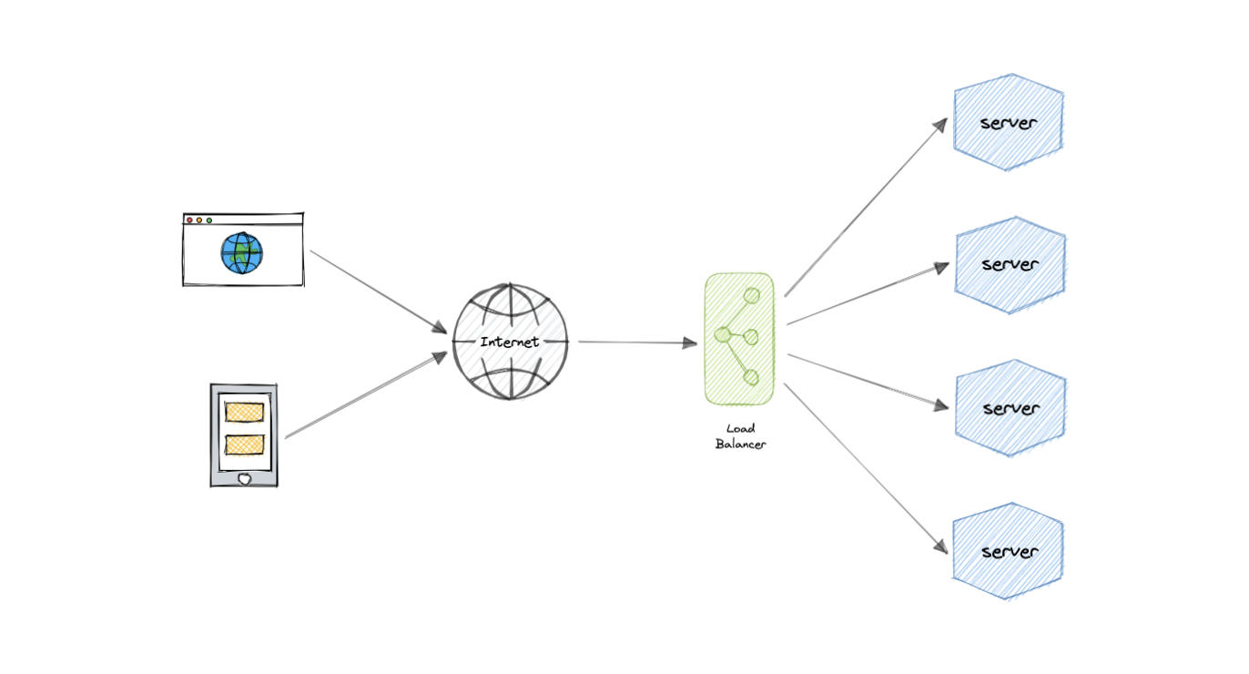
For additional scalability and redundancy, we can try to load balance at each layer of our system:

But why?
Modern high-traffic websites must serve hundreds of thousands, if not millions, of concurrent requests from users or clients. To cost-effectively scale to meet these high volumes, modern computing best practice generally requires adding more servers.
A load balancer can sit in front of the servers and route client requests across all servers capable of fulfilling those requests in a manner that maximizes speed and capacity utilization. This ensures that no single server is overworked, which could degrade performance. If a single server goes down, the load balancer redirects traffic to the remaining online servers. When a new server is added to the server group, the load balancer automatically starts sending requests to it.
Workload distribution
This is the core functionality provided by a load balancer and has several common variations:
- Host-based: Distributes requests based on the requested hostname.
- Path-based: Using the entire URL to distribute requests as opposed to just the hostname.
- Content-based: Inspects the message content of a request. This allows distribution based on content such as the value of a parameter.
Layers
Generally speaking, load balancers operate at one of the two levels:
Network layer
This is the load balancer that works at the network’s transport layer, also known as layer 4. This performs routing based on networking information such as IP addresses and is not able to perform content-based routing. These are often dedicated hardware devices that can operate at high speed.
Application layer
This is the load balancer that operates at the application layer, also known as layer 7. Load balancers can read requests in their entirety and perform content-based routing. This allows the management of load based on a full understanding of traffic.
Types
Let’s look at different types of load balancers:
Software
Software load balancers usually are easier to deploy than hardware versions. They also tend to be more cost-effective and flexible, and they are used in conjunction with software development environments. The software approach gives us the flexibility of configuring the load balancer to our environment’s specific needs. The boost in flexibility may come at the cost of having to do more work to set up the load balancer. Compared to hardware versions, which offer more of a closed-box approach, software balancers give us more freedom to make changes and upgrades.
Software load balancers are widely used and are available either as installable solutions that require configuration and management or as a managed cloud service.
Hardware
As the name implies, a hardware load balancer relies on physical, on-premises hardware to distribute application and network traffic. These devices can handle a large volume of traffic but often carry a hefty price tag and are fairly limited in terms of flexibility.
Hardware load balancers include proprietary firmware that requires maintenance and updates as new versions and security patches are released.
DNS
DNS load balancing is the practice of configuring a domain in the Domain Name System (DNS) such that client requests to the domain are distributed across a group of server machines.
Unfortunately, DNS load balancing has inherent problems limiting its reliability and efficiency. Most significantly, DNS does not check for server and network outages, or errors. It always returns the same set of IP addresses for a domain even if servers are down or inaccessible.
Routing Algorithms
Now, let’s discuss commonly used routing algorithms:
- Round-robin: Requests are distributed to application servers in rotation.
- Weighted Round-robin: Builds on the simple Round-robin technique to account for differing server characteristics such as compute and traffic handling capacity using weights that can be assigned via DNS records by the administrator.
- Least Connections: A new request is sent to the server with the fewest current connections to clients. The relative computing capacity of each server is factored into determining which one has the least connections.
- Least Response Time: Sends requests to the server selected by a formula that combines the fastest response time and fewest active connections.
- Least Bandwidth: This method measures traffic in megabits per second (Mbps), sending client requests to the server with the least Mbps of traffic.
- Hashing: Distributes requests based on a key we define, such as the client IP address or the request URL.
Advantages
Load balancing also plays a key role in preventing downtime, other advantages of load balancing include the following:
- Scalability
- Redundancy
- Flexibility
- Efficiency
Redundant load balancers
As you must’ve already guessed, the load balancer itself can be a single point of failure. To overcome this, a second or N number of load balancers can be used in a cluster mode.
And, if there’s a failure detection and the active load balancer fails, another passive load balancer can take over which will make our system more fault-tolerant.
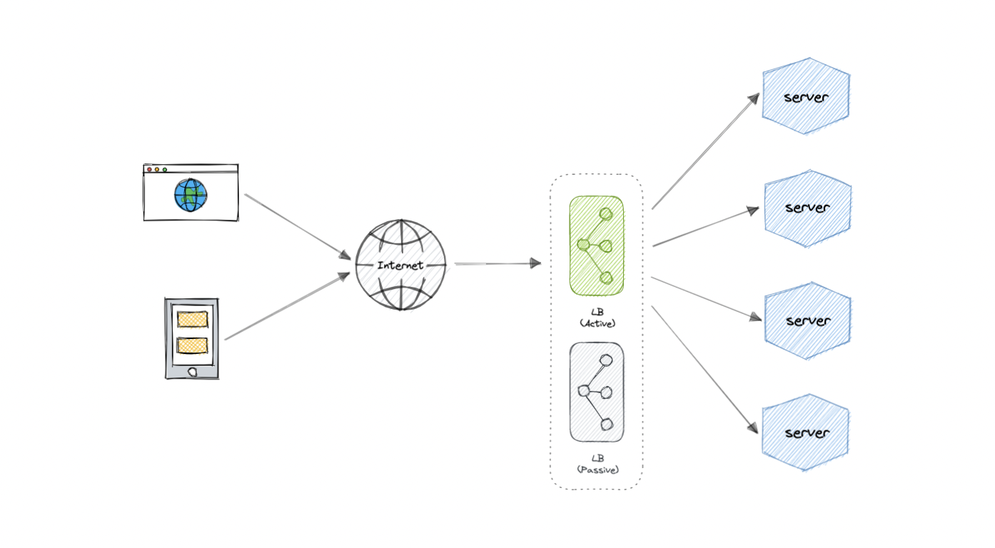
Features
Here are some commonly desired features of load balancers:
- Autoscaling: Starting up and shutting down resources in response to demand conditions.
- Sticky sessions: The ability to assign the same user or device to the same resource in order to maintain the session state on the resource.
- Healthchecks: The ability to determine if a resource is down or performing poorly in order to remove the resource from the load balancing pool.
- Persistence connections: Allowing a server to open a persistent connection with a client such as a WebSocket.
- Encryption: Handling encrypted connections such as TLS and SSL.
- Certificates: Presenting certificates to a client and authentication of client certificates.
- Compression: Compression of responses.
- Caching: An application-layer load balancer may offer the ability to cache responses.
- Logging: Logging of request and response metadata can serve as an important audit trail or source for analytics data.
- Request tracing: Assigning each request a unique id for the purposes of logging, monitoring, and troubleshooting.
- Redirects: The ability to redirect an incoming request based on factors such as the requested path.
- Fixed response: Returning a static response for a request such as an error message.
Examples
Following are some of the load balancing solutions commonly used in the industry:
- Amazon Elastic Load Balancing
- Azure Load Balancing
- GCP Load Balancing
- DigitalOcean Load Balancer
- Nginx
- HAProxy
Clustering
At a high level, a computer cluster is a group of two or more computers, or nodes, that run in parallel to achieve a common goal. This allows workloads consisting of a high number of individual, parallelizable tasks to be distributed among the nodes in the cluster. As a result, these tasks can leverage the combined memory and processing power of each computer to increase overall performance.
To build a computer cluster, the individual nodes should be connected to a network to enable internode communication. The software can then be used to join the nodes together and form a cluster. It may have a shared storage device and/or local storage on each node.
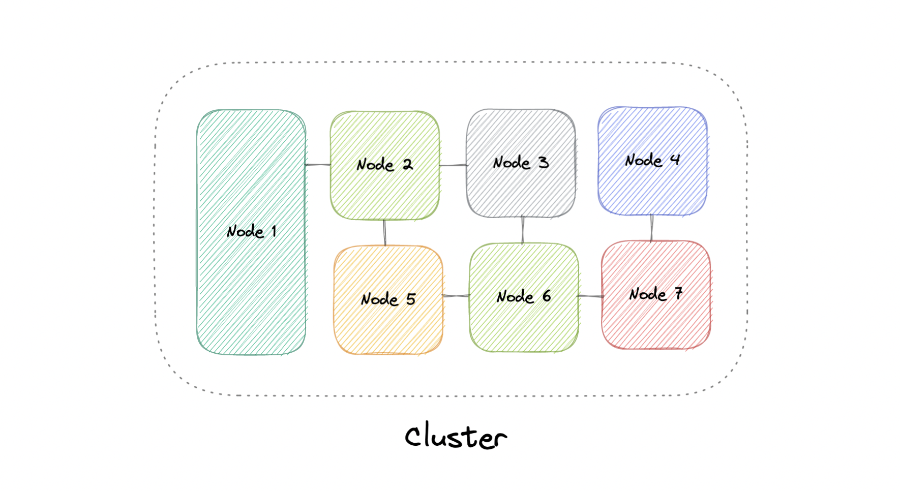
Typically, at least one node is designated as the leader node and acts as the entry point to the cluster. The leader node may be responsible for delegating incoming work to the other nodes and, if necessary, aggregating the results and returning a response to the user.
Ideally, a cluster functions as if it were a single system. A user accessing the cluster should not need to know whether the system is a cluster or an individual machine. Furthermore, a cluster should be designed to minimize latency and prevent bottlenecks in node-to-node communication.
Types
Computer clusters can generally be categorized into three types:
- Highly available or fail-over
- Load balancing
- High-performance computing
Configurations
The two most commonly used high availability (HA) clustering configurations are active-active and active-passive.
Active-Active
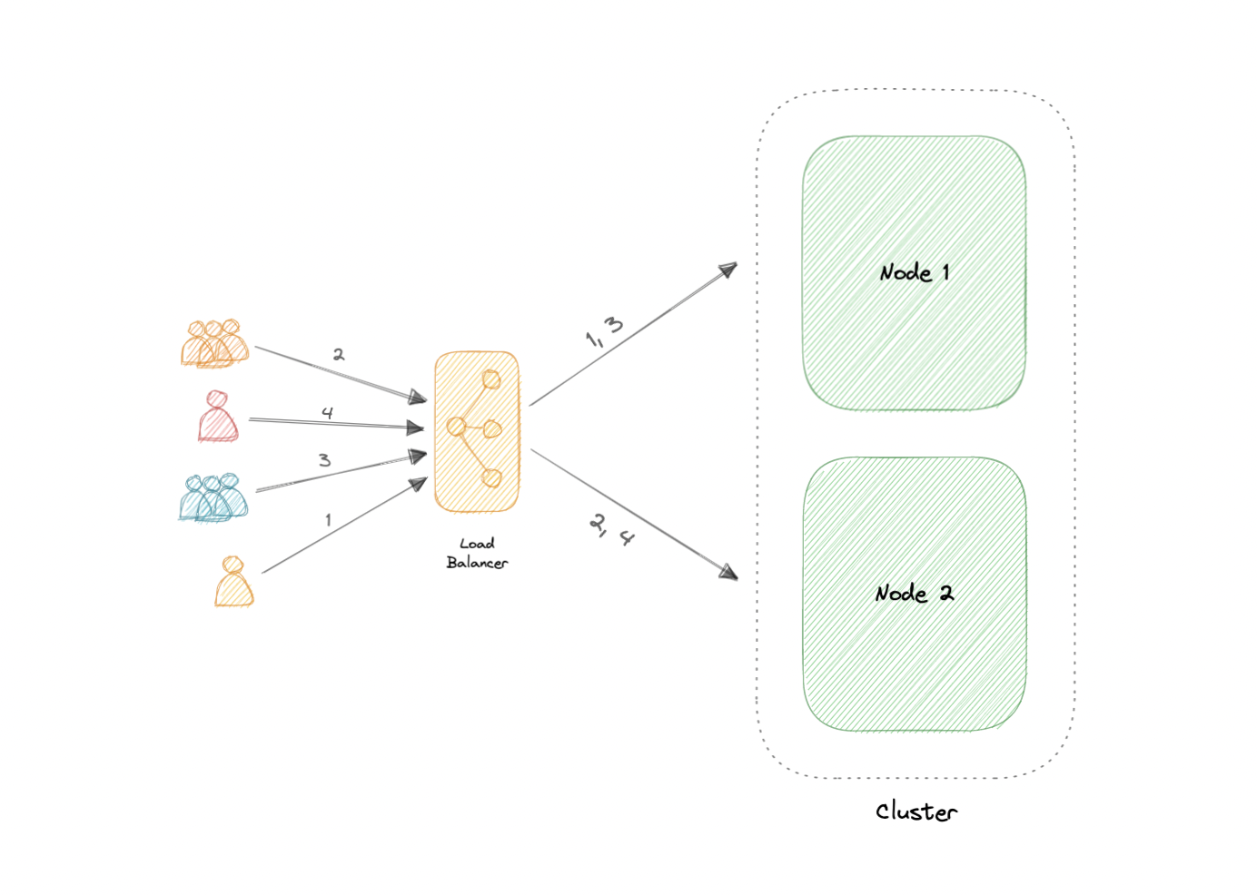
An active-active cluster is typically made up of at least two nodes, both actively running the same kind of service simultaneously. The main purpose of an active-active cluster is to achieve load balancing. A load balancer distributes workloads across all nodes to prevent any single node from getting overloaded. Because there are more nodes available to serve, there will also be an improvement in throughput and response times.
Active-Passive
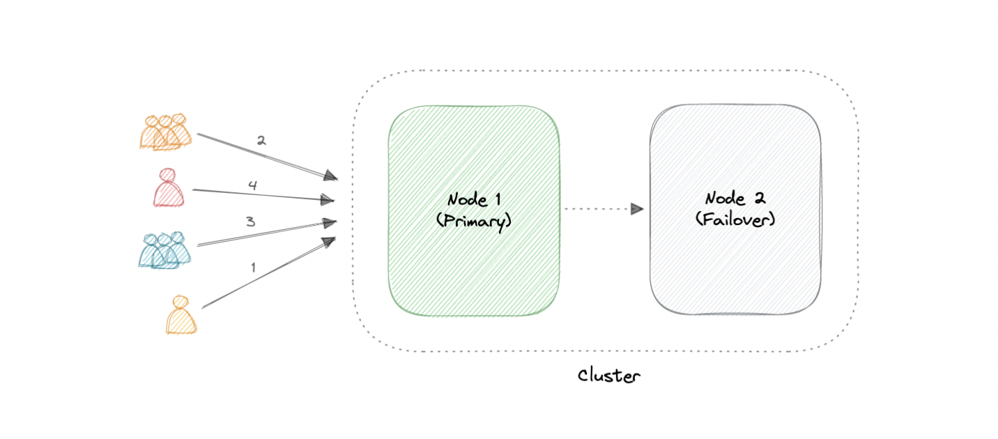
Like the active-active cluster configuration, an active-passive cluster also consists of at least two nodes. However, as the name active-passive implies, not all nodes are going to be active. For example, in the case of two nodes, if the first node is already active, then the second node must be passive or on standby.
Advantages
Four key advantages of cluster computing are as follows:
- High availability
- Scalability
- Performance
- Cost-effective
Load balancing vs Clustering
Load balancing shares some common traits with clustering, but they are different processes. Clustering provides redundancy and boosts capacity and availability. Servers in a cluster are aware of each other and work together toward a common purpose. But with load balancing, servers are not aware of each other. Instead, they react to the requests they receive from the load balancer.
We can employ load balancing in conjunction with clustering but it also is applicable in cases involving independent servers that share a common purpose such as to run a website, business application, web service, or some other IT resource.
Challenges
The most obvious challenge clustering presents is the increased complexity of installation and maintenance. An operating system, the application, and its dependencies must each be installed and updated on every node.
This becomes even more complicated if the nodes in the cluster are not homogeneous. Resource utilization for each node must also be closely monitored, and logs should be aggregated to ensure that the software is behaving correctly.
Additionally, storage becomes more difficult to manage, a shared storage device must prevent nodes from overwriting one another and distributed data stores have to be kept in sync.
Examples
Clustering is commonly used in the industry, and often many technologies offer some sort of clustering mode. For example:
- Containers (eg. Kubernetes, Amazon ECS)
- Databases (eg. Cassandra, MongoDB)
- Cache (eg. Redis)
Caching
“There are only two hard things in Computer Science: cache invalidation and naming things.” - Phil Karlton

A cache’s primary purpose is to increase data retrieval performance by reducing the need to access the underlying slower storage layer. Trading off capacity for speed, a cache typically stores a subset of data transiently, in contrast to databases whose data is usually complete and durable.
Caches take advantage of the locality of reference principle “recently requested data is likely to be requested again”.
Caching and Memory
Similar to a computer’s memory, a cache is a compact, fast-performing memory that stores data in a hierarchy of levels, starting at level one, and progressing from there sequentially. They are labeled as L1, L2, L3, and so on. A cache also gets written if requested, such as when there has been an update and new content needs to be saved to the cache, replacing the older content that was saved.
No matter whether the cache is read or written, it’s done one block at a time. Each block also has a tag that includes the location where the data was stored in the cache. When data is requested from the cache, a search occurs through the tags to find the specific content that’s needed in level one (L1) of the memory. If the correct data isn’t found, more searches are conducted in L2.
If the data isn’t found there, searches are continued in L3, then L4, and so on until it has been found, then, it’s read and loaded. If the data isn’t found in the cache at all, then it’s written into it for quick retrieval the next time.
Cache hit and Cache miss
Cache hit
A cache hit describes the situation where content is successfully served from the cache. The tags are searched in the memory rapidly, and when the data is found and read, it’s considered a cache hit.
Cold, Warm, and Hot Caches
A cache hit can also be described as cold, warm, or hot. In each of these, the speed at which the data is read is described.
A hot cache is an instance where data was read from the memory at the fastest possible rate. This happens when the data is retrieved from L1.
A cold cache is the slowest possible rate for data to be read, though, it’s still successful so it’s still considered a cache hit. The data is just found lower in the memory hierarchy such as in L3, or lower.
A warm cache is used to describe data that’s found in L2 or L3. It’s not as fast as a hot cache, but it’s still faster than a cold cache. Generally, calling a cache warm is used to express that it’s slower and closer to a cold cache than a hot one.
Cache miss
A cache miss refers to the instance when the memory is searched and the data isn’t found. When this happens, the content is transferred and written into the cache.
Cache Invalidation
Cache invalidation is a process where the computer system declares the cache entries as invalid and removes or replaces them. If the data is modified, it should be invalidated in the cache, if not, this can cause inconsistent application behavior. There are three kinds of caching systems:
Write-through cache

Data is written into the cache and the corresponding database simultaneously.
Pro: Fast retrieval, complete data consistency between cache and storage.
Con: Higher latency for write operations.
Write-around cache

Where write directly goes to the database or permanent storage, bypassing the cache.
Pro: This may reduce latency.
Con: It increases cache misses because the cache system has to read the information from the database in case of a cache miss. As a result, this can lead to higher read latency in the case of applications that write and re-read the information quickly. Read happen from slower back-end storage and experiences higher latency.
Write-back cache

Where the write is only done to the caching layer and the write is confirmed as soon as the write to the cache completes. The cache then asynchronously syncs this write to the database.
Pro: This would lead to reduced latency and high throughput for write-intensive applications.
Con: There is a risk of data loss in case the caching layer crashes. We can improve this by having more than one replica acknowledging the write in the cache.
Eviction policies
Following are some of the most common cache eviction policies:
- First In First Out (FIFO): The cache evicts the first block accessed first without any regard to how often or how many times it was accessed before.
- Last In First Out (LIFO): The cache evicts the block accessed most recently first without any regard to how often or how many times it was accessed before.
- Least Recently Used (LRU): Discards the least recently used items first.
- Most Recently Used (MRU): Discards, in contrast to LRU, the most recently used items first.
- Least Frequently Used (LFU): Counts how often an item is needed. Those that are used least often are discarded first.
- Random Replacement (RR): Randomly selects a candidate item and discards it to make space when necessary.
Distributed Cache
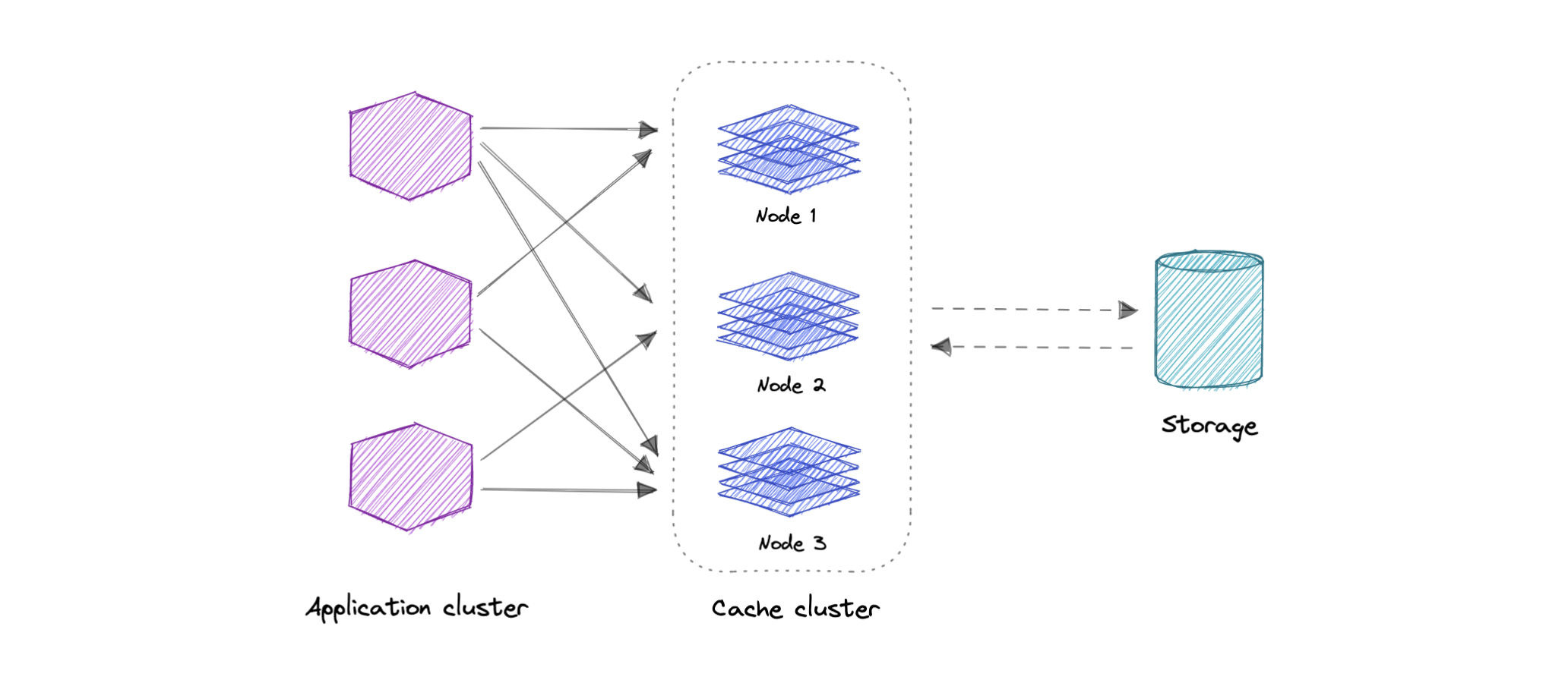
A distributed cache is a system that pools together the random-access memory (RAM) of multiple networked computers into a single in-memory data store used as a data cache to provide fast access to data. While most caches are traditionally in one physical server or hardware component, a distributed cache can grow beyond the memory limits of a single computer by linking together multiple computers.
Global Cache
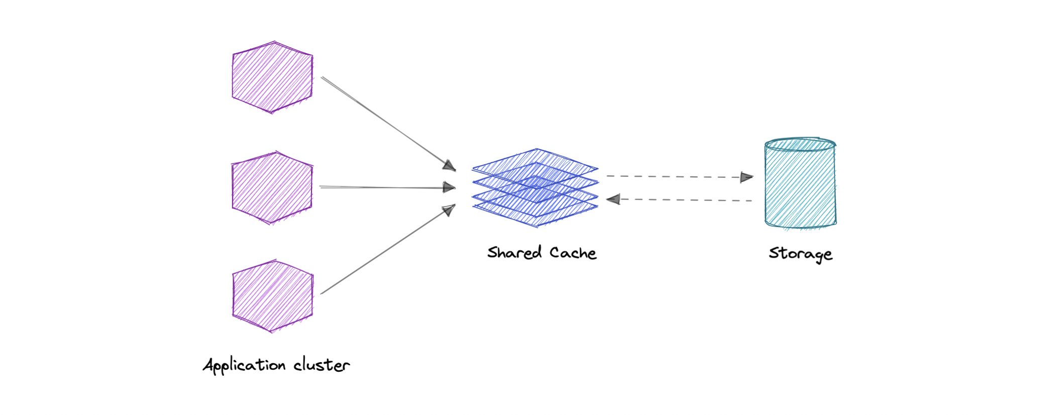
As the name suggests, we will have a single shared cache that all the application nodes will use. When the requested data is not found in the global cache, it’s the responsibility of the cache to find out the missing piece of data from the underlying data store.
Use cases
Caching can have many real-world use cases such as:
- Database Caching
- Content Delivery Network (CDN)
- Domain Name System (DNS) Caching
- API Caching
When not to use caching?
Let’s also look at some scenarios where we should not use cache:
- Caching isn’t helpful when it takes just as long to access the cache as it does to access the primary data store.
- Caching doesn’t work as well when requests have low repetition (higher randomness), because caching performance comes from repeated memory access patterns.
- Caching isn’t helpful when the data changes frequently, as the cached version gets out of sync, and the primary data store must be accessed every time.
It’s important to note that a cache should not be used as permanent data storage. They are almost always implemented in volatile memory because it is faster, and thus should be considered transient.
Advantages
Below are some advantages of caching:
- Improves performance
- Reduce latency
- Reduce load on the database
- Reduce network cost
- Increase Read Throughput
Examples
Here are some commonly used technologies for caching:
Content Delivery Network (CDN)
A content delivery network (CDN) is a geographically distributed group of servers that work together to provide fast delivery of internet content. Generally, static files such as HTML/CSS/JS, photos, and videos are served from CDN.
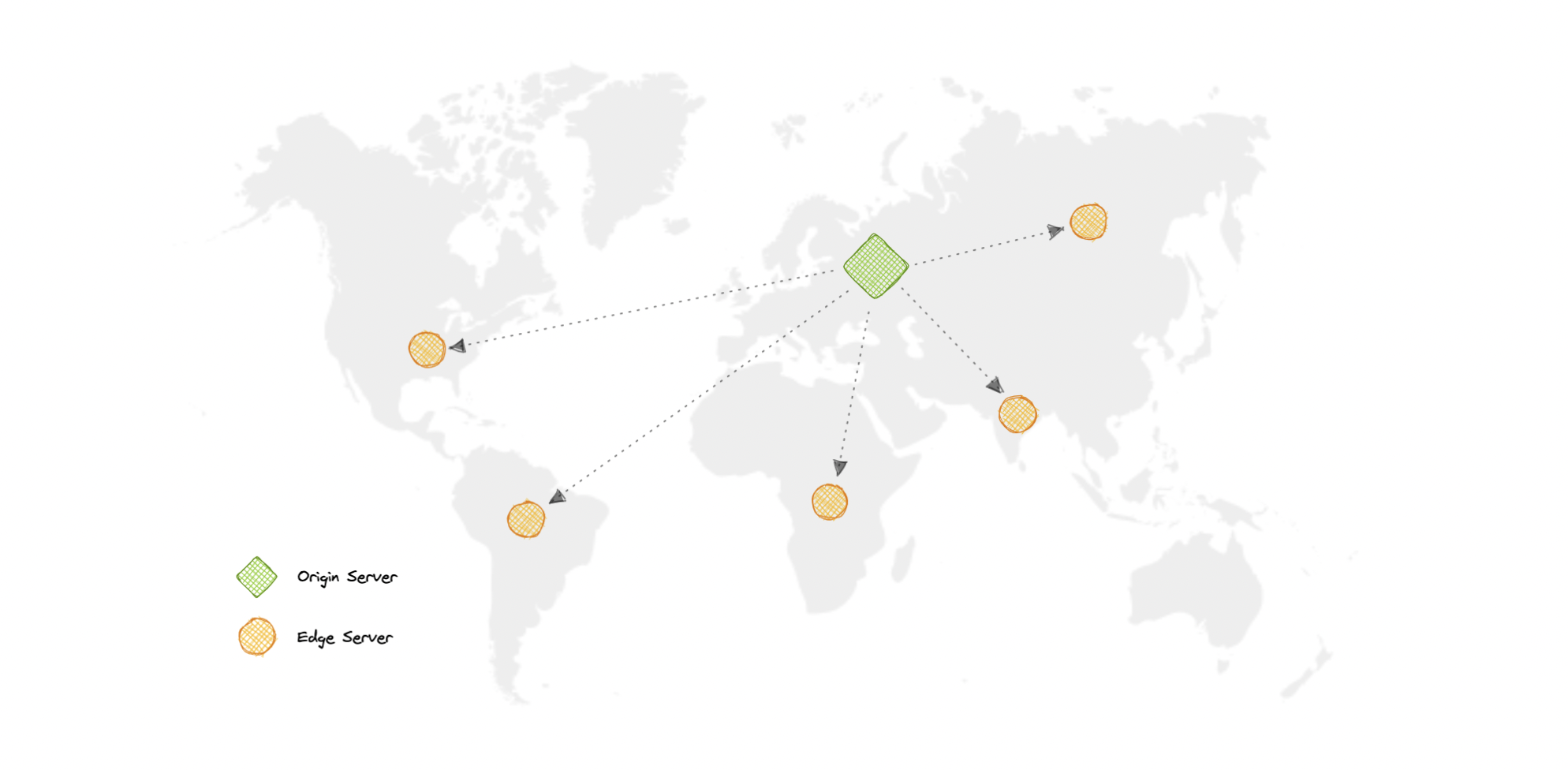
Why use a CDN?
Content Delivery Network (CDN) increases content availability and redundancy while reducing bandwidth costs and improving security. Serving content from CDNs can significantly improve performance as users receive content from data centers close to them and our servers do not have to serve requests that the CDN fulfills.
How does a CDN work?
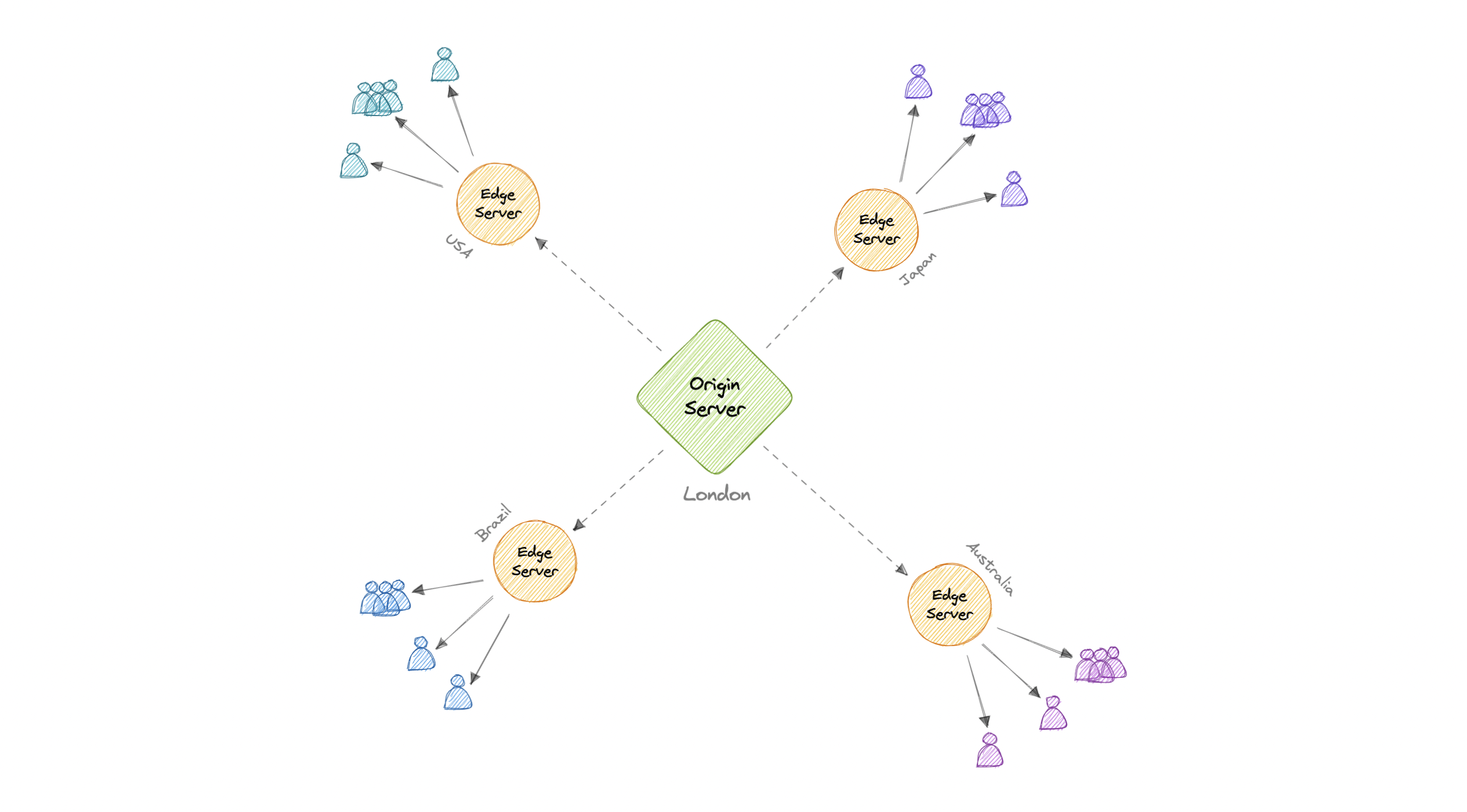
In a CDN, the origin server contains the original versions of the content while the edge servers are numerous and distributed across various locations around the world.
To minimize the distance between the visitors and the website’s server, a CDN stores a cached version of its content in multiple geographical locations known as edge locations. Each edge location contains a number of caching servers responsible for content delivery to visitors within its proximity.
Once the static assets are cached on all the CDN servers for a particular location, all subsequent website visitor requests for static assets will be delivered from these edge servers instead of the origin, thus reducing origin load and improving scalability.
For example, when someone in the UK requests our website which might be hosted in the USA, they will be served from the closest edge location such as the London edge location. This is much quicker than having the visitor make a complete request to the origin server which will increase the latency.
Types
CDNs are generally divided into two types:
Push CDNs
Push CDNs receive new content whenever changes occur on the server. We take full responsibility for providing content, uploading directly to the CDN, and rewriting URLs to point to the CDN. We can configure when content expires and when it is updated. Content is uploaded only when it is new or changed, minimizing traffic, but maximizing storage.
Sites with a small amount of traffic or sites with content that isn’t often updated work well with push CDNs. Content is placed on the CDNs once, instead of being re-pulled at regular intervals.
Pull CDNs
In a Pull CDN situation, the cache is updated based on request. When the client sends a request that requires static assets to be fetched from the CDN if the CDN doesn’t have it, then it will fetch the newly updated assets from the origin server and populate its cache with this new asset, and then send this new cached asset to the user.
Contrary to the Push CDN, this requires less maintenance because cache updates on CDN nodes are performed based on requests from the client to the origin server. Sites with heavy traffic work well with pull CDNs, as traffic is spread out more evenly with only recently-requested content remaining on the CDN.
Disadvantages
As we all know good things come with extra costs, so let’s discuss some disadvantages of CDNs:
- Extra charges: It can be expensive to use a CDN, especially for high-traffic services.
- Restrictions: Some organizations and countries have blocked the domains or IP addresses of popular CDNs.
- Location: If most of our audience is located in a country where the CDN has no servers, the data on our website may have to travel further than without using any CDN.
Examples
Here are some widely used CDNs:
Proxy
A proxy server is an intermediary piece of hardware/software sitting between the client and the backend server. It receives requests from clients and relays them to the origin servers. Typically, proxies are used to filter requests, log requests, or sometimes transform requests (by adding/removing headers, encrypting/decrypting, or compression).
Types
There are two types of proxies:
Forward Proxy
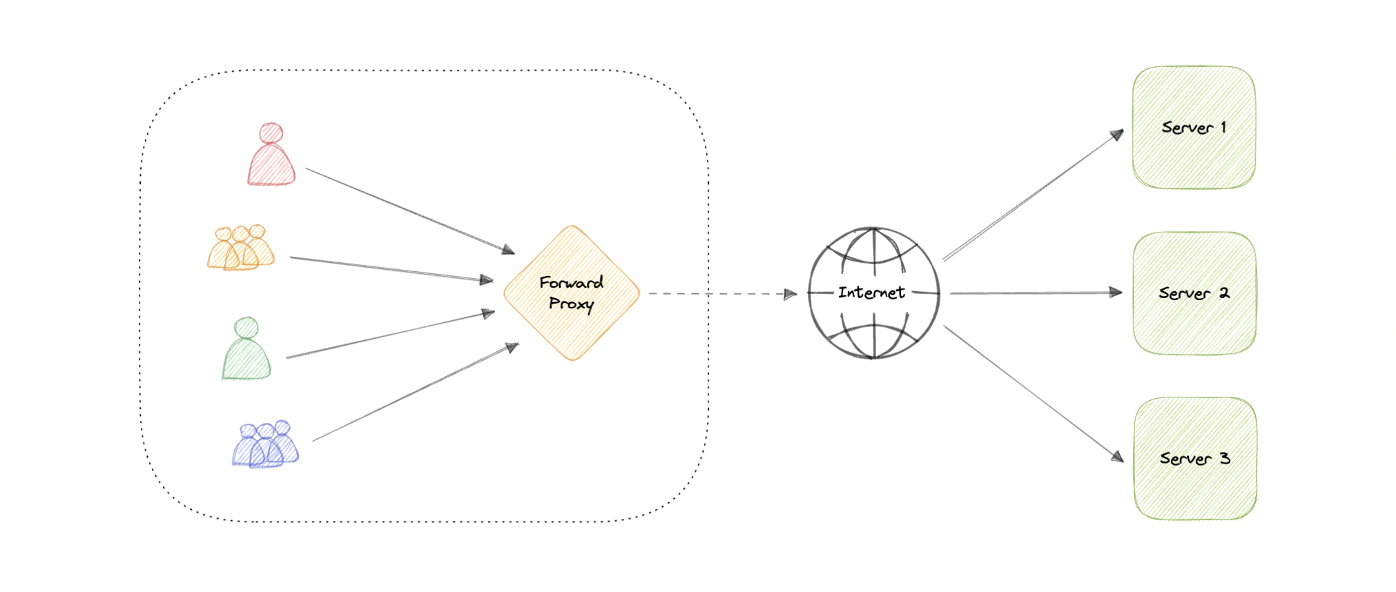
A forward proxy, often called a proxy, proxy server, or web proxy is a server that sits in front of a group of client machines. When those computers make requests to sites and services on the internet, the proxy server intercepts those requests and then communicates with web servers on behalf of those clients, like a middleman.
Advantages
Here are some advantages of a forward proxy:
- Block access to certain content
- Allows access to geo-restricted content
- Provides anonymity
- Avoid other browsing restrictions
Although proxies provide the benefits of anonymity, they can still track our personal information. Setup and maintenance of a proxy server can be costly and requires configurations.
Reverse Proxy
A reverse proxy is a server that sits in front of one or more web servers, intercepting requests from clients. When clients send requests to the origin server of a website, those requests are intercepted by the reverse proxy server.
The difference between a forward and reverse proxy is subtle but important. A simplified way to sum it up would be to say that a forward proxy sits in front of a client and ensures that no origin server ever communicates directly with that specific client. On the other hand, a reverse proxy sits in front of an origin server and ensures that no client ever communicates directly with that origin server.
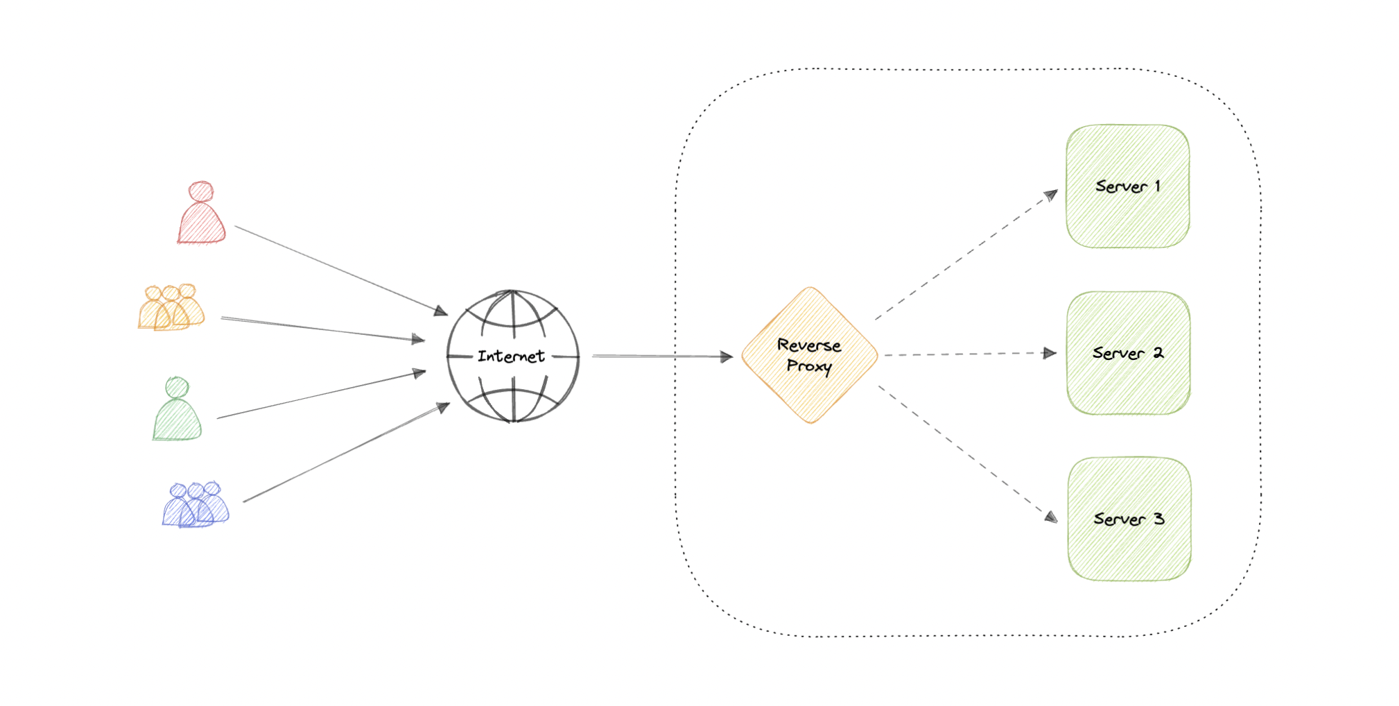
Introducing reverse proxy results in increased complexity. A single reverse proxy is a single point of failure, configuring multiple reverse proxies (i.e. a failover) further increases complexity.
Advantages
Here are some advantages of using a reverse proxy:
- Improved security
- Caching
- SSL encryption
- Load balancing
- Scalability and flexibility
Load balancer vs Reverse Proxy
Wait, isn’t reverse proxy similar to a load balancer? Well, no as a load balancer is useful when we have multiple servers. Often, load balancers route traffic to a set of servers serving the same function, while, reverse proxies can be useful even with just one web server or application server. A reverse proxy can also act as a load balancer but not the other way around.
Examples
Below are some commonly used proxy technologies:
Availability
Availability is the time a system remains operational to perform its required function in a specific period. It is a simple measure of the percentage of time that a system, service, or machine remains operational under normal conditions.
The Nine’s of availability
Availability is often quantified by uptime (or downtime) as a percentage of time the service is available. It is generally measured in the number of 9s.
\[Availability = \frac{Uptime}{(Uptime + Downtime)}\]If availability is 99.00% available, it is said to have “2 nines” of availability, and if it is 99.9%, it is called “3 nines”, and so on.
| Availability (Percent) | Downtime (Year) | Downtime (Month) | Downtime (Week) |
|---|---|---|---|
| 90% (one nine) | 36.53 days | 72 hours | 16.8 hours |
| 99% (two nines) | 3.65 days | 7.20 hours | 1.68 hours |
| 99.9% (three nines) | 8.77 hours | 43.8 minutes | 10.1 minutes |
| 99.99% (four nines) | 52.6 minutes | 4.32 minutes | 1.01 minutes |
| 99.999% (five nines) | 5.25 minutes | 25.9 seconds | 6.05 seconds |
| 99.9999% (six nines) | 31.56 seconds | 2.59 seconds | 604.8 milliseconds |
| 99.99999% (seven nines) | 3.15 seconds | 263 milliseconds | 60.5 milliseconds |
| 99.999999% (eight nines) | 315.6 milliseconds | 26.3 milliseconds | 6 milliseconds |
| 99.9999999% (nine nines) | 31.6 milliseconds | 2.6 milliseconds | 0.6 milliseconds |
Availability in Sequence vs Parallel
If a service consists of multiple components prone to failure, the service’s overall availability depends on whether the components are in sequence or in parallel.
Sequence
Overall availability decreases when two components are in sequence.
\[Availability \space (Total) = Availability \space (Foo) * Availability \space (Bar)\]For example, if both Foo and Bar each had 99.9% availability, their total availability in sequence would be 99.8%.
Parallel
Overall availability increases when two components are in parallel.
\[Availability \space (Total) = 1 - (1 - Availability \space (Foo)) * (1 - Availability \space (Bar))\]For example, if both Foo and Bar each had 99.9% availability, their total availability in parallel would be 99.9999%.
Availability vs Reliability
If a system is reliable, it is available. However, if it is available, it is not necessarily reliable. In other words, high reliability contributes to high availability, but it is possible to achieve high availability even with an unreliable system.
High availability vs Fault Tolerance
Both high availability and fault tolerance apply to methods for providing high uptime levels. However, they accomplish the objective differently.
A fault-tolerant system has no service interruption but a significantly higher cost, while a highly available system has minimal service interruption. Fault-tolerance requires full hardware redundancy as if the main system fails, with no loss in uptime, another system should take over.
Scalability
Scalability is the measure of how well a system responds to changes by adding or removing resources to meet demands.
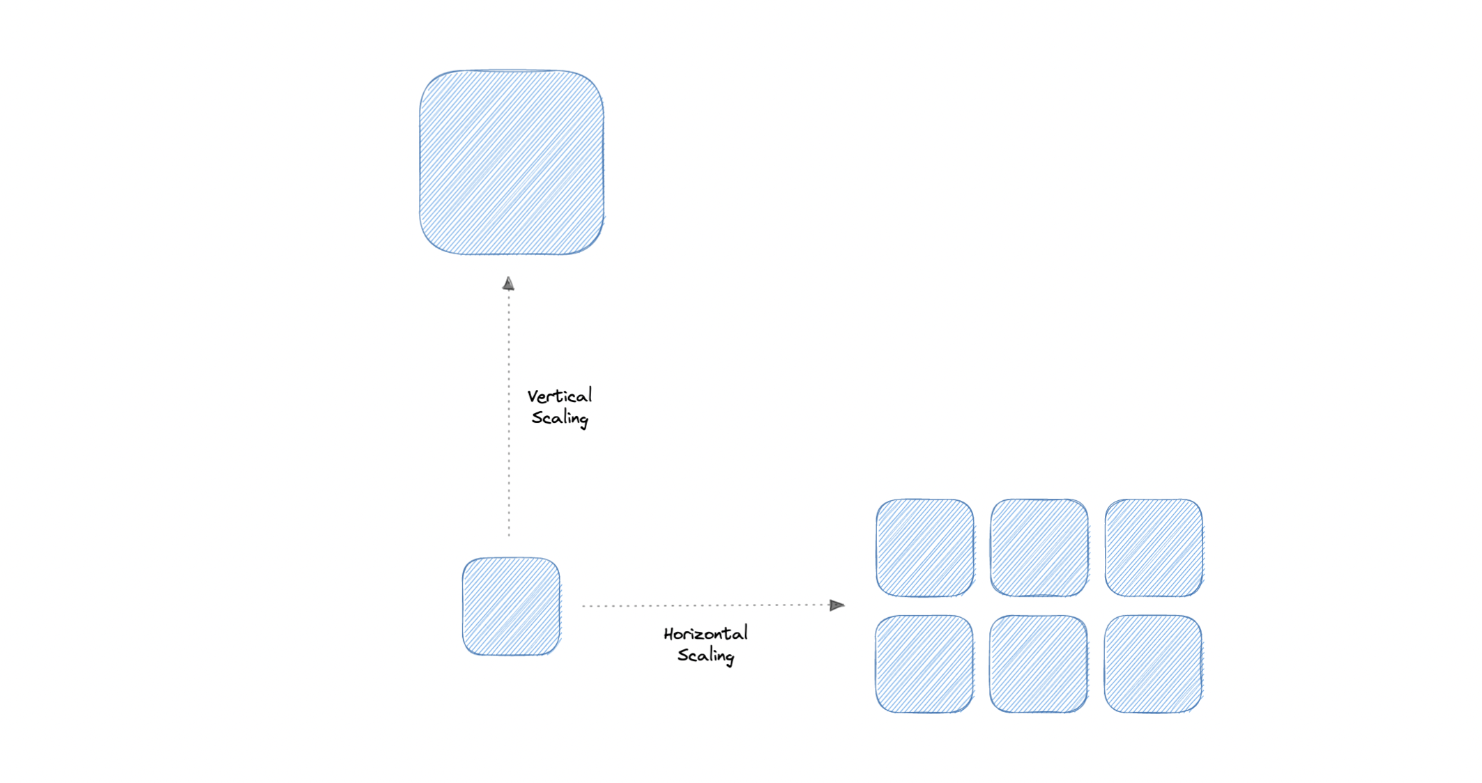
Let’s discuss different types of scaling:
Vertical scaling
Vertical scaling (also known as scaling up) expands a system’s scalability by adding more power to an existing machine. In other words, vertical scaling refers to improving an application’s capability via increasing hardware capacity.
Advantages
- Simple to implement
- Easier to manage
- Data consistent
Disadvantages
- Risk of high downtime
- Harder to upgrade
- Can be a single point of failure
Horizontal scaling
Horizontal scaling (also known as scaling out) expands a system’s scale by adding more machines. It improves the performance of the server by adding more instances to the existing pool of servers, allowing the load to be distributed more evenly.
Advantages
- Increased redundancy
- Better fault tolerance
- Flexible and efficient
- Easier to upgrade
Disadvantages
- Increased complexity
- Data inconsistency
- Increased load on downstream services
Storage
Storage is a mechanism that enables a system to retain data, either temporarily or permanently. This topic is mostly skipped over in the context of system design, however, it is important to have a basic understanding of some common types of storage techniques that can help us fine-tune our storage components. Let’s discuss some important storage concepts:
RAID
RAID (Redundant Array of Independent Disks) is a way of storing the same data on multiple hard disks or solid-state drives (SSDs) to protect data in the case of a drive failure.
There are different RAID levels, however, and not all have the goal of providing redundancy. Let’s discuss some commonly used RAID levels:
- RAID 0: Also known as striping, data is split evenly across all the drives in the array.
- RAID 1: Also known as mirroring, at least two drives contains the exact copy of a set of data. If a drive fails, others will still work.
- RAID 5: Striping with parity. Requires the use of at least 3 drives, striping the data across multiple drives like RAID 0, but also has a parity distributed across the drives.
- RAID 6: Striping with double parity. RAID 6 is like RAID 5, but the parity data are written to two drives.
- RAID 10: Combines striping plus mirroring from RAID 0 and RAID 1. It provides security by mirroring all data on secondary drives while using striping across each set of drives to speed up data transfers.
Comparison
Let’s compare all the features of different RAID levels:
| Features | RAID 0 | RAID 1 | RAID 5 | RAID 6 | RAID 10 |
|---|---|---|---|---|---|
| Description | Striping | Mirroring | Striping with Parity | Striping with double parity | Striping and Mirroring |
| Minimum Disks | 2 | 2 | 3 | 4 | 4 |
| Read Performance | High | High | High | High | High |
| Write Performance | High | Medium | High | High | Medium |
| Cost | Low | High | Low | Low | High |
| Fault Tolerance | None | Single-drive failure | Single-drive failure | Two-drive failure | Up to one disk failure in each sub-array |
| Capacity Utilization | 100% | 50% | 67%-94% | 50%-80% | 50% |
Volumes
Volume is a fixed amount of storage on a disk or tape. The term volume is often used as a synonym for the storage itself, but it is possible for a single disk to contain more than one volume or a volume to span more than one disk.
File storage
File storage is a solution to store data as files and present it to its final users as a hierarchical directories structure. The main advantage is to provide a user-friendly solution to store and retrieve files. To locate a file in file storage, the complete path of the file is required. It is economical and easily structured and is usually found on hard drives, which means that they appear exactly the same for the user and on the hard drive.
Example: Amazon EFS, Azure files, Google Cloud Filestore, etc.
Block storage
Block storage divides data into blocks (chunks) and stores them as separate pieces. Each block of data is given a unique identifier, which allows a storage system to place the smaller pieces of data wherever it is most convenient.
Block storage also decouples data from user environments, allowing that data to be spread across multiple environments. This creates multiple paths to the data and allows the user to retrieve it quickly. When a user or application requests data from a block storage system, the underlying storage system reassembles the data blocks and presents the data to the user or application
Example: Amazon EBS.
Object Storage
Object storage, which is also known as object-based storage, breaks data files up into pieces called objects. It then stores those objects in a single repository, which can be spread out across multiple networked systems.
Example: Amazon S3, Azure Blob Storage, Google Cloud Storage, etc.
NAS
A NAS (Network Attached Storage) is a storage device connected to a network that allows storage and retrieval of data from a central location for authorized network users. NAS devices are flexible, meaning that as we need additional storage, we can add to what we have. It’s faster, less expensive, and provides all the benefits of a public cloud on-site, giving us complete control.
HDFS
The Hadoop Distributed File System (HDFS) is a distributed file system designed to run on commodity hardware. HDFS is highly fault-tolerant and is designed to be deployed on low-cost hardware. HDFS provides high throughput access to application data and is suitable for applications that have large data sets. It has many similarities with existing distributed file systems.
HDFS is designed to reliably store very large files across machines in a large cluster. It stores each file as a sequence of blocks, all blocks in a file except the last block are the same size. The blocks of a file are replicated for fault tolerance.
Databases and DBMS
What is a Database?
A database is an organized collection of structured information, or data, typically stored electronically in a computer system. A database is usually controlled by a Database Management System (DBMS). Together, the data and the DBMS, along with the applications that are associated with them, are referred to as a database system, often shortened to just database.
What is DBMS?
A database typically requires a comprehensive database software program known as a Database Management System (DBMS). A DBMS serves as an interface between the database and its end-users or programs, allowing users to retrieve, update, and manage how the information is organized and optimized. A DBMS also facilitates oversight and control of databases, enabling a variety of administrative operations such as performance monitoring, tuning, and backup and recovery.
Components
Here are some common components found across different databases:
Schema
The role of a schema is to define the shape of a data structure, and specify what kinds of data can go where. Schemas can be strictly enforced across the entire database, loosely enforced on part of the database, or they might not exist at all.
Table
Each table contains various columns just like in a spreadsheet. A table can have as meager as two columns and upwards of a hundred or more columns, depending upon the kind of information being put in the table.
Column
A column contains a set of data values of a particular type, one value for each row of the database. A column may contain text values, numbers, enums, timestamps, etc.
Row
Data in a table is recorded in rows. There can be thousands or millions of rows in a table having any particular information.
Types

Below are different types of databases:
SQL and NoSQL databases are broad topics and will be discussed separately in SQL databases and NoSQL databases. Learn how they compare to each other in SQL vs NoSQL databases.
Challenges
Some common challenges faced while running databases at scale:
- Absorbing significant increases in data volume: The explosion of data coming in from sensors, connected machines, and dozens of other sources.
- Ensuring data security: Data breaches are happening everywhere these days, it’s more important than ever to ensure that data is secure but also easily accessible to users.
- Keeping up with demand: Companies need real-time access to their data to support timely decision-making and to take advantage of new opportunities.
- Managing and maintaining the database and infrastructure: As databases become more complex and data volumes grow, companies are faced with the expense of hiring additional talent to manage their databases.
- Removing limits on scalability: A business needs to grow if it’s going to survive, and its data management must grow along with it. But it’s very difficult to predict how much capacity the company will need, particularly with on-premises databases.
- Ensuring data residency, data sovereignty, or latency requirements: Some organizations have use cases that are better suited to run on-premises. In those cases, engineered systems that are pre-configured and pre-optimized for running the database are ideal.
SQL databases
A SQL (or relational) database is a collection of data items with pre-defined relationships between them. These items are organized as a set of tables with columns and rows. Tables are used to hold information about the objects to be represented in the database. Each column in a table holds a certain kind of data and a field stores the actual value of an attribute. The rows in the table represent a collection of related values of one object or entity.
Each row in a table could be marked with a unique identifier called a primary key, and rows among multiple tables can be made related using foreign keys. This data can be accessed in many different ways without re-organizing the database tables themselves. SQL databases usually follow the ACID consistency model.
Materialized views
A materialized view is a pre-computed data set derived from a query specification and stored for later use. Because the data is pre-computed, querying a materialized view is faster than executing a query against the base table of the view. This performance difference can be significant when a query is run frequently or is sufficiently complex.
It also enables data subsetting and improves the performance of complex queries that run on large data sets which reduces network loads. There are other uses of materialized views, but they are mostly used for performance and replication.
N+1 query problem
The N+1 query problem happens when the data access layer executes N additional SQL statements to fetch the same data that could have been retrieved when executing the primary SQL query. The larger the value of N, the more queries will be executed, the larger the performance impact.
This is commonly seen in GraphQL and ORM (Object-Relational Mapping) tools and can be addressed by optimizing the SQL query or using a dataloader that batches consecutive requests and makes a single data request under the hood.
Advantages
Let’s look at some advantages of using relational databases:
- Simple and accurate
- Accessibility
- Data consistency
- Flexibility
Disadvantages
Below are the disadvantages of relational databases:
- Expensive to maintain
- Difficult schema evolution
- Performance hits (join, denormalization, etc.)
- Difficult to scale due to poor horizontal scalability
Examples
Here are some commonly used relational databases:
NoSQL databases
NoSQL is a broad category that includes any database that doesn’t use SQL as its primary data access language. These types of databases are also sometimes referred to as non-relational databases. Unlike in relational databases, data in a NoSQL database doesn’t have to conform to a pre-defined schema. NoSQL databases follow BASE consistency model.
Below are different types of NoSQL databases:
Document
A document database (also known as a document-oriented database or a document store) is a database that stores information in documents. They are general-purpose databases that serve a variety of use cases for both transactional and analytical applications.
Advantages
- Intuitive and flexible
- Easy horizontal scaling
- Schemaless
Disadvantages
- Schemaless
- Non-relational
Examples
Key-value
One of the simplest types of NoSQL databases, key-value databases save data as a group of key-value pairs made up of two data items each. They’re also sometimes referred to as a key-value store.
Advantages
- Simple and performant
- Highly scalable for high volumes of traffic
- Session management
- Optimized lookups
Disadvantages
- Basic CRUD
- Values can’t be filtered
- Lacks indexing and scanning capabilities
- Not optimized for complex queries
Examples
Graph
A graph database is a NoSQL database that uses graph structures for semantic queries with nodes, edges, and properties to represent and store data instead of tables or documents.
The graph relates the data items in the store to a collection of nodes and edges, the edges representing the relationships between the nodes. The relationships allow data in the store to be linked together directly and, in many cases, retrieved with one operation.
Advantages
- Query speed
- Agile and flexible
- Explicit data representation
Disadvantages
- Complex
- No standardized query language
Use cases
- Fraud detection
- Recommendation engines
- Social networks
- Network mapping
Examples
Time series
A time-series database is a database optimized for time-stamped, or time series, data.
Advantages
- Fast insertion and retrieval
- Efficient data storage
Use cases
- IoT data
- Metrics analysis
- Application monitoring
- Understand financial trends
Examples
Wide column
Wide column databases, also known as wide column stores, are schema-agnostic. Data is stored in column families, rather than in rows and columns.
Advantages
- Highly scalable, can handle petabytes of data
- Ideal for real-time big data applications
Disadvantages
- Expensive
- Increased write time
Use cases
- Business analytics
- Attribute-based data storage
Examples
Multi-model
Multi-model databases combine different database models (i.e. relational, graph, key-value, document, etc.) into a single, integrated backend. This means they can accommodate various data types, indexes, queries, and store data in more than one model.
Advantages
- Flexibility
- Suitable for complex projects
- Data consistent
Disadvantages
- Complex
- Less mature
Examples
SQL vs NoSQL databases
In the world of databases, there are two main types of solutions, SQL (relational) and NoSQL (non-relational) databases. Both of them differ in the way they were built, the kind of information they store, and how they store it. Relational databases are structured and have predefined schemas while non-relational databases are unstructured, distributed, and have a dynamic schema.
High-level differences
Here are some high-level differences between SQL and NoSQL:
Storage
SQL stores data in tables, where each row represents an entity and each column represents a data point about that entity.
NoSQL databases have different data storage models such as key-value, graph, document, etc.
Schema
In SQL, each record conforms to a fixed schema, meaning the columns must be decided and chosen before data entry and each row must have data for each column. The schema can be altered later, but it involves modifying the database using migrations.
Whereas in NoSQL, schemas are dynamic. Fields can be added on the fly, and each record (or equivalent) doesn’t have to contain data for each field.
Querying
SQL databases use SQL (structured query language) for defining and manipulating the data, which is very powerful.
In a NoSQL database, queries are focused on a collection of documents. Different databases have different syntax for querying.
Scalability
In most common situations, SQL databases are vertically scalable, which can get very expensive. It is possible to scale a relational database across multiple servers, but this is a challenging and time-consuming process.
On the other hand, NoSQL databases are horizontally scalable, meaning we can add more servers easily to our NoSQL database infrastructure to handle large traffic. Any cheap commodity hardware or cloud instances can host NoSQL databases, thus making it a lot more cost-effective than vertical scaling. A lot of NoSQL technologies also distribute data across servers automatically.
Reliability
The vast majority of relational databases are ACID compliant. So, when it comes to data reliability and a safe guarantee of performing transactions, SQL databases are still the better bet.
Most of the NoSQL solutions sacrifice ACID compliance for performance and scalability.
Reasons
As always we should always pick the technology that fits the requirements better. So, let’s look at some reasons for picking SQL or NoSQL based database:
For SQL
- Structured data with strict schema
- Relational data
- Need for complex joins
- Transactions
- Lookups by index are very fast
For NoSQL
- Dynamic or flexible schema
- Non-relational data
- No need for complex joins
- Very data-intensive workload
- Very high throughput for IOPS
Database Replication
Replication is a process that involves sharing information to ensure consistency between redundant resources such as multiple databases, to improve reliability, fault-tolerance, or accessibility.
Master-Slave Replication
The master serves reads and writes, replicating writes to one or more slaves, which serve only reads. Slaves can also replicate additional slaves in a tree-like fashion. If the master goes offline, the system can continue to operate in read-only mode until a slave is promoted to a master or a new master is provisioned.
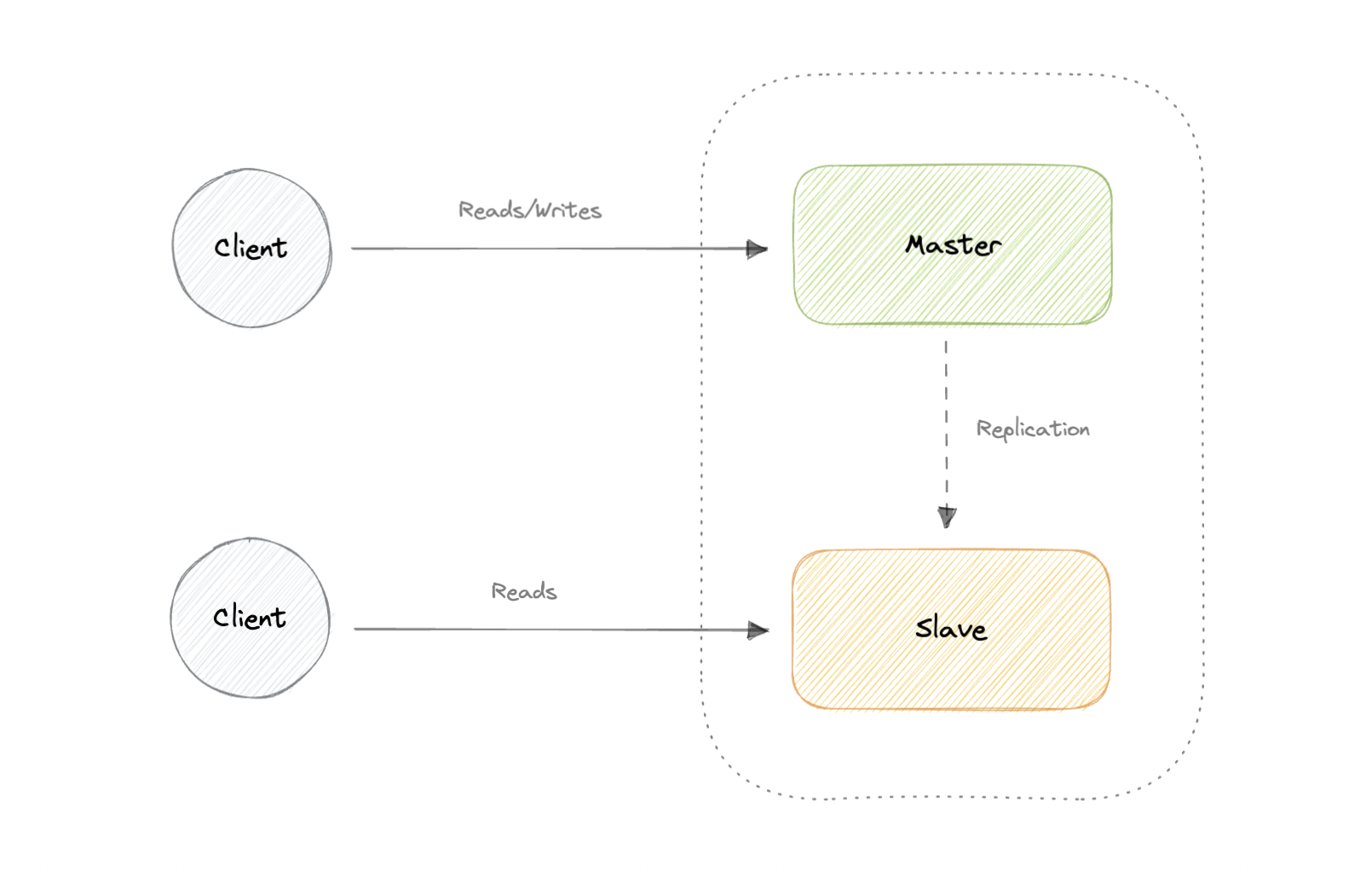
Advantages
- Backups of the entire database of relatively no impact on the master.
- Applications can read from the slave(s) without impacting the master.
- Slaves can be taken offline and synced back to the master without any downtime.
Disadvantages
- Replication adds more hardware and additional complexity.
- Downtime and possibly loss of data when a master fails.
- All writes also have to be made to the master in a master-slave architecture.
- The more read slaves, the more we have to replicate, which will increase replication lag.
Master-Master Replication
Both masters serve reads/writes and coordinate with each other. If either master goes down, the system can continue to operate with both reads and writes.
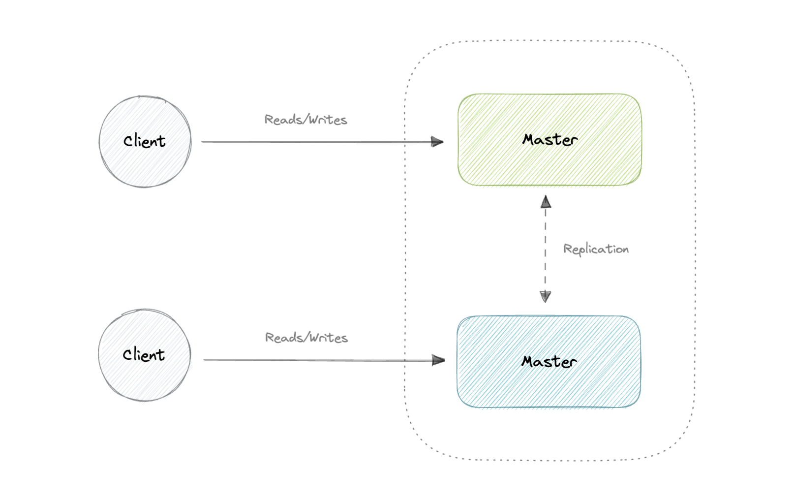
Advantages
- Applications can read from both masters.
- Distributes write load across both master nodes.
- Simple, automatic, and quick failover.
Disadvantages
- Not as simple as master-slave to configure and deploy.
- Either loosely consistent or have increased write latency due to synchronization.
- Conflict resolution comes into play as more write nodes are added and as latency increases.
Synchronous vs Asynchronous replication
The primary difference between synchronous and asynchronous replication is how the data is written to the replica. In synchronous replication, data is written to primary storage and the replica simultaneously. As such, the primary copy and the replica should always remain synchronized.
In contrast, asynchronous replication copies the data to the replica after the data is already written to the primary storage. Although the replication process may occur in near-real-time, it is more common for replication to occur on a scheduled basis and it is more cost-effective.
Indexes
Indexes are well known when it comes to databases, they are used to improve the speed of data retrieval operations on the data store. An index makes the trade-offs of increased storage overhead, and slower writes (since we not only have to write the data but also have to update the index) for the benefit of faster reads. Indexes are used to quickly locate data without having to examine every row in a database table. Indexes can be created using one or more columns of a database table, providing the basis for both rapid random lookups and efficient access to ordered records.

An index is a data structure that can be perceived as a table of contents that points us to the location where actual data lives. So when we create an index on a column of a table, we store that column and a pointer to the whole row in the index. Indexes are also used to create different views of the same data. For large data sets, this is an excellent way to specify different filters or sorting schemes without resorting to creating multiple additional copies of the data.
One quality that database indexes can have is that they can be dense or sparse. Each of these index qualities comes with its own trade-offs. Let’s look at how each index type would work:
Dense Index
In a dense index, an index record is created for every row of the table. Records can be located directly as each record of the index holds the search key value and the pointer to the actual record.

Dense indexes require more maintenance than sparse indexes at write-time. Since every row must have an entry, the database must maintain the index on inserts, updates, and deletes. Having an entry for every row also means that dense indexes will require more memory. The benefit of a dense index is that values can be quickly found with just a binary search. Dense indexes also do not impose any ordering requirements on the data.
Sparse Index
In a sparse index, records are created only for some of the records.

Sparse indexes require less maintenance than dense indexes at write-time since they only contain a subset of the values. This lighter maintenance burden means that inserts, updates, and deletes will be faster. Having fewer entries also means that the index will use less memory. Finding data is slower since a scan across the page typically follows the binary search. Sparse indexes are also optional when working with ordered data.
Normalization and Denormalization
Terms
Before we go any further, let’s look at some commonly used terms in normalization and denormalization.
Keys
Primary key: Column or group of columns that can be used to uniquely identify every row of the table.
Composite key: A primary key made up of multiple columns.
Super key: Set of all keys that can uniquely identify all the rows present in a table.
Candidate key: Attributes that identify rows uniquely in a table.
Foreign key: It is a reference to a primary key of another table.
Alternate key: Keys that are not primary keys are known as alternate keys.
Surrogate key: A system-generated value that uniquely identifies each entry in a table when no other column was able to hold properties of a primary key.
Dependencies
Partial dependency: Occurs when the primary key determines some other attributes.
Functional dependency: It is a relationship that exists between two attributes, typically between the primary key and non-key attribute within a table.
Transitive functional dependency: Occurs when some non-key attribute determines some other attribute.
Anomalies
Database anomaly happens when there is a flaw in the database due to incorrect planning or storing everything in a flat database. This is generally addressed by the process of normalization.
There are three types of database anomalies:
Insertion anomaly: Occurs when we are not able to insert certain attributes in the database without the presence of other attributes.
Update anomaly: Occurs in case of data redundancy and partial update. In other words, a correct update of the database needs other actions such as addition, deletion, or both.
Deletion anomaly: Occurs where deletion of some data requires deletion of other data.
Example
Let’s consider the following table which is not normalized:
| ID | Name | Role | Team |
|---|---|---|---|
| 1 | Peter | Software Engineer | A |
| 2 | Brian | DevOps Engineer | B |
| 3 | Hailey | Product Manager | C |
| 4 | Hailey | Product Manager | C |
| 5 | Steve | Frontend Engineer | D |
Let’s imagine, we hired a new person “John” but they might not be assigned a team immediately. This will cause an insertion anomaly as the team attribute is not yet present.
Next, let’s say Hailey from Team C got promoted, to reflect that change in the database, we will need to update 2 rows to maintain consistency which can cause an update anomaly.
Finally, we would like to remove Team B but to do that we will also need to remove additional information such as name and role, this is an example of a deletion anomaly.
Normalization
Normalization is the process of organizing data in a database. This includes creating tables and establishing relationships between those tables according to rules designed both to protect the data and to make the database more flexible by eliminating redundancy and inconsistent dependency.
Why do we need normalization?
The goal of normalization is to eliminate redundant data and ensure data is consistent. A fully normalized database allows its structure to be extended to accommodate new types of data without changing the existing structure too much. As a result, applications interacting with the database are minimally affected.
Normal forms
Normal forms are a series of guidelines to ensure that the database is normalized. Let’s discuss some essential normal forms:
1NF
For a table to be in the first normal form (1NF), it should follow the following rules:
- Repeating groups are not permitted.
- Identify each set of related data with a primary key.
- Set of related data should have a separate table.
- Mixing data types in the same column is not permitted.
2NF
For a table to be in the second normal form (2NF), it should follow the following rules:
- Satisfies the first normal form (1NF).
- Should not have any partial dependency.
3NF
For a table to be in the third normal form (3NF), it should follow the following rules:
- Satisfies the second normal form (2NF).
- Transitive functional dependencies are not permitted.
BCNF
Boyce-Codd normal form (or BCNF) is a slightly stronger version of the third normal form (3NF) used to address certain types of anomalies not dealt with by 3NF as originally defined. Sometimes it is also known as the 3.5 normal form (3.5NF).
For a table to be in the Boyce-Codd normal form (BCNF), it should follow the following rules:
- Satisfied the third normal form (3NF).
- For every functional dependency X → Y, X should be the super key.
There are more normal forms such as 4NF, 5NF, and 6NF but we won’t discuss them here. Check out this amazing video that goes into detail.
In a relational database, a relation is often described as “normalized” if it meets the third normal form. Most 3NF relations are free of insertion, update, and deletion anomalies.
As with many formal rules and specifications, real-world scenarios do not always allow for perfect compliance. If you decide to violate one of the first three rules of normalization, make sure that your application anticipates any problems that could occur, such as redundant data and inconsistent dependencies.
Advantages
Here are some advantages of normalization:
- Reduces data redundancy.
- Better data design.
- Increases data consistency.
- Enforces referential integrity.
Disadvantages
Let’s look at some disadvantages of normalization:
- Data design is complex.
- Slower performance.
- Maintenance overhead.
- Require more joins.
Denormalization
Denormalization is a database optimization technique in which we add redundant data to one or more tables. This can help us avoid costly joins in a relational database. It attempts to improve read performance at the expense of some write performance. Redundant copies of the data are written in multiple tables to avoid expensive joins.
Once data becomes distributed with techniques such as federation and sharding, managing joins across the network further increases complexity. Denormalization might circumvent the need for such complex joins.
Note: Denormalization does not mean reversing normalization.
Advantages
Let’s look at some advantages of denormalization:
- Retrieving data is faster.
- Writing queries is easier.
- Reduction in number of tables.
- Convenient to manage.
Disadvantages
Below are some disadvantages of denormalization:
- Expensive inserts and updates.
- Increases complexity of database design.
- Increases data redundancy.
- More chances of data inconsistency.
ACID and BASE consistency models
Let’s discuss the ACID and BASE consistency models.
ACID
The term ACID stands for Atomicity, Consistency, Isolation, and Durability. ACID properties are used for maintaining data integrity during transaction processing.
In order to maintain consistency before and after a transaction relational databases follow ACID properties. Let us understand these terms:
Atomic
All operations in a transaction succeed or every operation is rolled back.
Consistent
On the completion of a transaction, the database is structurally sound.
Isolated
Transactions do not contend with one another. Contentious access to data is moderated by the database so that transactions appear to run sequentially.
Durable
Once the transaction has been completed and the writes and updates have been written to the disk, it will remain in the system even if a system failure occurs.
BASE
With the increasing amount of data and high availability requirements, the approach to database design has also changed dramatically. To increase the ability to scale and at the same time be highly available, we move the logic from the database to separate servers. In this way, the database becomes more independent and focused on the actual process of storing data.
In the NoSQL database world, ACID transactions are less common as some databases have loosened the requirements for immediate consistency, data freshness, and accuracy in order to gain other benefits, like scale and resilience.
BASE properties are much looser than ACID guarantees, but there isn’t a direct one-for-one mapping between the two consistency models. Let us understand these terms:
Basic Availability
The database appears to work most of the time.
Soft-state
Stores don’t have to be write-consistent, nor do different replicas have to be mutually consistent all the time.
Eventual consistency
The data might not be consistent immediately but eventually, it becomes consistent. Reads in the system are still possible even though they may not give the correct response due to inconsistency.
ACID vs BASE Trade-offs
There’s no right answer to whether our application needs an ACID or a BASE consistency model. Both the models have been designed to satisfy different requirements. While choosing a database we need to keep the properties of both the models and the requirements of our application in mind.
Given BASE’s loose consistency, developers need to be more knowledgeable and rigorous about consistent data if they choose a BASE store for their application. It’s essential to be familiar with the BASE behavior of the chosen database and work within those constraints.
On the other hand, planning around BASE limitations can sometimes be a major disadvantage when compared to the simplicity of ACID transactions. A fully ACID database is the perfect fit for use cases where data reliability and consistency are essential.
CAP Theorem
Video: https://youtu.be/8UryASGBiR4
CAP theorem states that a distributed system can deliver only two of the three desired characteristics Consistency, Availability, and Partition tolerance (CAP).
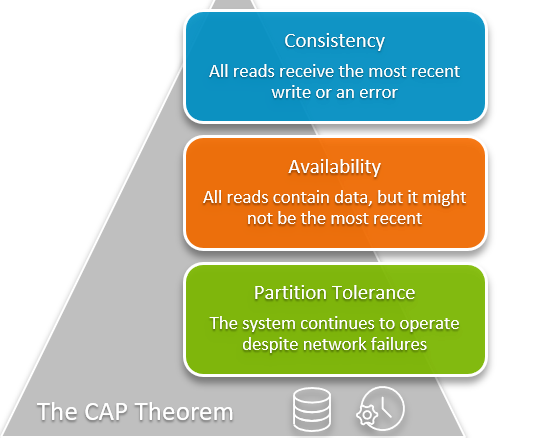
Consistency
In a consistent system, all nodes see the same data simultaneously. If we perform a read operation on a consistent system, it should return the value of the most recent write operation. The read should cause all nodes to return the same data. All users see the same data at the same time, regardless of the node they connect to. When data is written to a single node, it is then replicated across the other nodes in the system. For this to happen, whenever data is written to one node, it must be instantly forwarded or replicated across all the nodes in the system before the write is deemed “successful”.
Financial data is a good example. When a user logs in to their banking institution, they do not want to see an error that no data is returned, or that the value is higher or lower than it actually is. Banking apps should return the exact value of a user’s account information. In this case, banks would rely on consistent databases.
Examples of a consistent database include:
- Bank account balances
- Text messages
Database options for consistency:
- MongoDB
- Redis
- HBase
Availability
When availability is present in a distributed system, it means that the system remains operational all of the time. Every request will get a response regardless of the individual state of the nodes. This means that the system will operate even if there are multiple nodes down. Unlike a consistent system, there’s no guarantee that the response will be the most recent write operation.
Example of a highly available database:
- On YouTube and social media like Facebook and Instagram, we can ignore consistency in views or likes count but the availability of videos and posts is essential.
- In e-commerce businesses. Online stores want to make their store and the functions of the shopping cart available 24/7 so shoppers can make purchases exactly when they need.
Database options for availability:
- Cassandra
- DynamoDB
- Cosmos DB
Partition tolerance
When a distributed system encounters a partition, it means that there’s a break in communication between nodes. If a system is partition-tolerant, the system does not fail, regardless of whether messages are dropped or delayed between nodes within the system. To have partition tolerance, the system must replicate records across combinations of nodes and networks.
CAP theorem NoSQL databases
NoSQL databases can be classified based on whether they support high availability or high consistency. NoSQL databases are great for distributed networks. They allow for horizontal scaling, and they can quickly scale across multiple nodes. When deciding which NoSQL database to use, it’s important to keep the CAP theorem in mind. NoSQL databases can be classified based on the two CAP features they support.
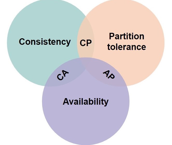
Consistency-Availability Tradeoff
We live in a physical world and can’t guarantee the stability of a network, so distributed databases must choose Partition Tolerance (P). This implies a tradeoff between Consistency (C) and Availability (A).
CA database
Relational databases, such as PostgreSQL, allow for consistency and availability if the systems are vertically scale on a single machine, we can avoid fault tolerance. A CA database delivers consistency and availability across all nodes. It can’t do this if there is a partition between any two nodes in the system, and therefore can’t deliver fault tolerance.
Example: PostgreSQL, MariaDB.
CP database
CP databases enable consistency and partition tolerance, but not availability. When a partition occurs, the system has to turn off inconsistent nodes until the partition can be fixed. That’s why they are not 100% available. MongoDB is an example of a CP database. It’s a NoSQL database management system (DBMS) that uses documents for data storage. It’s considered schema-less, which means that it doesn’t require a defined database schema. It’s commonly used in big data and applications running in different locations. The CP system is structured so that there’s only one primary node that receives all of the write requests in a given replica set. Secondary nodes replicate the data in the primary nodes, so if the primary node fails, a secondary node can stand-in. Example: MongoDB, Apache HBase.
AP database
AP databases enable availability and partition tolerance, but not consistency. In the event of a partition, all nodes are available, but they’re not all updated. For example, if a user tries to access data from a bad node, they won’t receive the most up-to-date version of the data. When the partition is eventually resolved, most AP databases will sync the nodes to ensure consistency across them. Apache Cassandra is an example of an AP database. It’s a NoSQL database with no primary node, meaning that all of the nodes remain available. Cassandra allows for eventual consistency because users can resync their data right after a partition is resolved.
Example: Apache Cassandra, CouchDB.
CAP theorem and microservices
Microservices are defined as loosely coupled services that can be independently developed, deployed, and maintained. They include their own stack, database, and database model, and communicate with each other through a network. Microservices have become especially popular in hybrid cloud and multi-cloud environments, and they are also widely used in on-premises data centers. If you want to create a microservices application, you can use the CAP theorem to help you determine a database that will best fit your needs.
PACELC Theorem
The PACELC theorem is an extension of the CAP theorem. The CAP theorem states that in the case of network partitioning (P) in a distributed system, one has to choose between Availability (A) and Consistency (C).
PACELC extends the CAP theorem by introducing latency (L) as an additional attribute of a distributed system. The theorem states that else (E), even when the system is running normally in the absence of partitions, one has to choose between latency (L) and consistency (C).
The PACELC theorem was first described by Daniel J. Abadi.
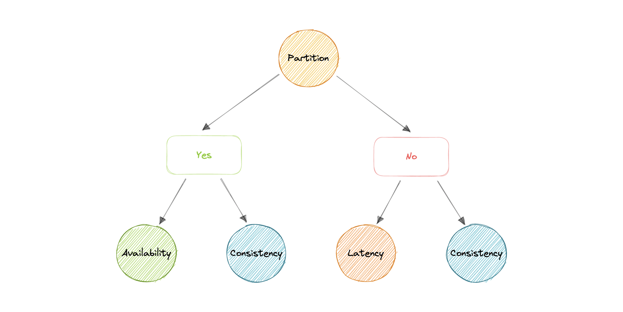
PACELC theorem was developed to address a key limitation of the CAP theorem as it makes no provision for performance or latency.
For example, according to the CAP theorem, a database can be considered Available if a query returns a response after 30 days. Obviously, such latency would be unacceptable for any real-world application.
Transactions
A transaction is a series of database operations that are considered to be a “single unit of work”. The operations in a transaction either all succeed, or they all fail. In this way, the notion of a transaction supports data integrity when part of a system fails. Not all databases choose to support ACID transactions, usually because they are prioritizing other optimizations that are hard or theoretically impossible to implement together.
Usually, relational databases support ACID transactions, and non-relational databases don’t (there are exceptions).
States
A transaction in a database can be in one of the following states:
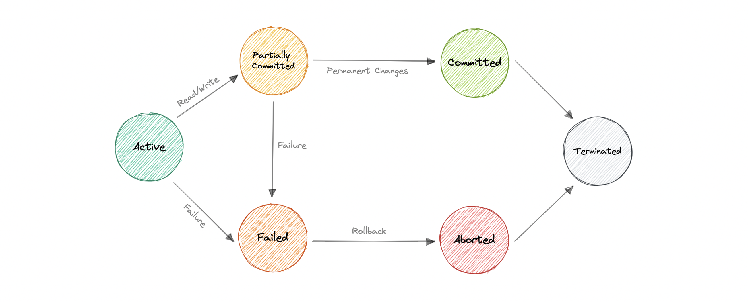
Active
In this state, the transaction is being executed. This is the initial state of every transaction.
Partially Committed
When a transaction executes its final operation, it is said to be in a partially committed state.
Committed
If a transaction executes all its operations successfully, it is said to be committed. All its effects are now permanently established on the database system.
Failed
The transaction is said to be in a failed state if any of the checks made by the database recovery system fails. A failed transaction can no longer proceed further.
Aborted
If any of the checks fail and the transaction has reached a failed state, then the recovery manager rolls back all its write operations on the database to bring the database back to its original state where it was prior to the execution of the transaction. Transactions in this state are aborted.
The database recovery module can select one of the two operations after a transaction aborts:
- Restart the transaction
- Kill the transaction
Terminated
If there isn’t any roll-back or the transaction comes from the committed state, then the system is consistent and ready for a new transaction and the old transaction is terminated.
Distributed Transactions
A distributed transaction is a set of operations on data that is performed across two or more databases. It is typically coordinated across separate nodes connected by a network, but may also span multiple databases on a single server.
Why do we need distributed transactions?
Unlike an ACID transaction on a single database, a distributed transaction involves altering data on multiple databases. Consequently, distributed transaction processing is more complicated, because the database must coordinate the committing or rollback of the changes in a transaction as a self-contained unit.
In other words, all the nodes must commit, or all must abort and the entire transaction rolls back. This is why we need distributed transactions.
Now, let’s look at some popular solutions for distributed transactions:
Two-Phase commit
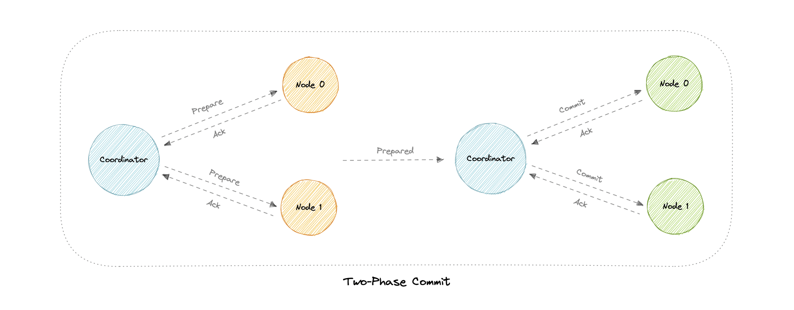
The two-phase commit (2PC) protocol is a distributed algorithm that coordinates all the processes that participate in a distributed transaction on whether to commit or abort (roll back) the transaction.
This protocol achieves its goal even in many cases of temporary system failure and is thus widely used. However, it is not resilient to all possible failure configurations, and in rare cases, manual intervention is needed to remedy an outcome.
This protocol requires a coordinator node, which basically coordinates and oversees the transaction across different nodes. The coordinator tries to establish the consensus among a set of processes in two phases, hence the name.
Phases
Two-phase commit consists of the following phases:
Prepare phase
The prepare phase involves the coordinator node collecting consensus from each of the participant nodes. The transaction will be aborted unless each of the nodes responds that they’re prepared.
Commit phase
If all participants respond to the coordinator that they are prepared, then the coordinator asks all the nodes to commit the transaction. If a failure occurs, the transaction will be rolled back.
Problems
Following problems may arise in the two-phase commit protocol:
- What if one of the nodes crashes?
- What if the coordinator itself crashes?
- It is a blocking protocol.
Three-phase commit

Three-phase commit (3PC) is an extension of the two-phase commit where the commit phase is split into two phases. This helps with the blocking problem that occurs in the two-phase commit protocol.
Phases
Three-phase commit consists of the following phases:
Prepare phase
This phase is the same as the two-phase commit.
Pre-commit phase
Coordinator issues the pre-commit message and all the participating nodes must acknowledge it. If a participant fails to receive this message in time, then the transaction is aborted.
Commit phase
This step is also similar to the two-phase commit protocol.
Why is the Pre-commit phase helpful?
The pre-commit phase accomplishes the following:
- If the participant nodes are found in this phase, that means that every participant has completed the first phase. The completion of prepare phase is guaranteed.
- Every phase can now time out and avoid indefinite waits.
Sagas
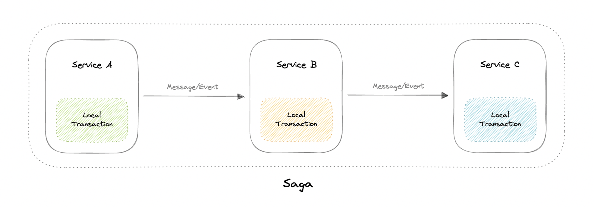
A saga is a sequence of local transactions. Each local transaction updates the database and publishes a message or event to trigger the next local transaction in the saga. If a local transaction fails because it violates a business rule then the saga executes a series of compensating transactions that undo the changes that were made by the preceding local transactions.
Coordination
There are two common implementation approaches:
- Choreography: Each local transaction publishes domain events that trigger local transactions in other services.
- Orchestration: An orchestrator tells the participants what local transactions to execute.
Problems
- The Saga pattern is particularly hard to debug.
- There’s a risk of cyclic dependency between saga participants.
- Lack of participant data isolation imposes durability challenges.
- Testing is difficult because all services must be running to simulate a transaction.
Sharding
Before we discuss sharding, let’s talk about data partitioning:
Data Partitioning
Data partitioning is a technique to break up a database into many smaller parts. It is the process of splitting up a database or a table across multiple machines to improve the manageability, performance, and availability of a database.
Methods
There are many different ways one could use to decide how to break up an application database into multiple smaller DBs. Below are three of the most popular methods used by various large-scale applications:
Horizontal Partitioning (or Sharding)
In this strategy, we split the table data horizontally based on the range of values defined by the partition key. It is also referred to as database sharding.
Vertical Partitioning
In vertical partitioning, we partition the data vertically based on columns. We divide tables into relatively smaller tables with few elements, and each part is present in a separate partition.
In this tutorial, we will specifically focus on sharding.
What is sharding?
Sharding is a database architecture pattern related to horizontal partitioning, which is the practice of separating one table’s rows into multiple different tables, known as partitions or shards. Each partition has the same schema and columns, but also a subset of the shared data. Likewise, the data held in each is unique and independent of the data held in other partitions.
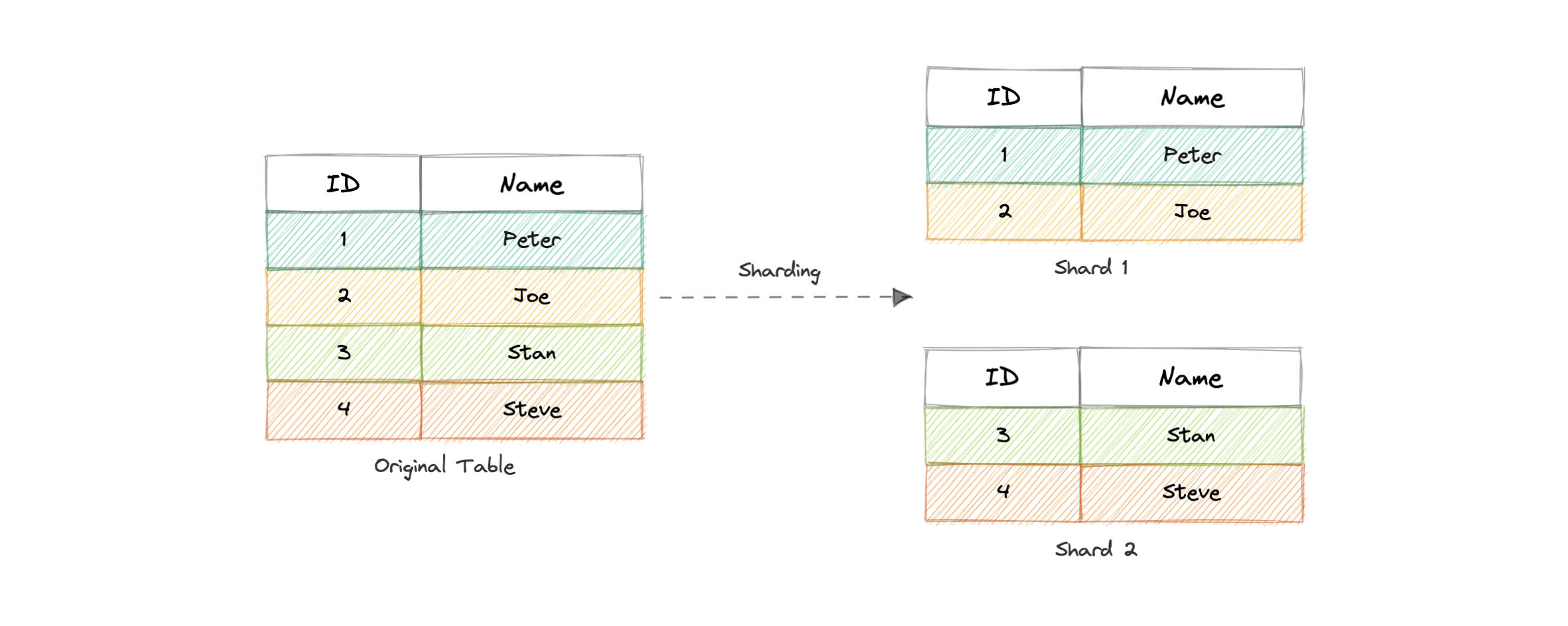
The justification for data sharding is that, after a certain point, it is cheaper and more feasible to scale horizontally by adding more machines than to scale it vertically by adding powerful servers. Sharding can be implemented at both application or the database level.
Partitioning criteria
There are a large number of criteria available for data partitioning. Some most commonly used criteria are:
Hash-Based
This strategy divides the rows into different partitions based on a hashing algorithm rather than grouping database rows based on continuous indexes.
The disadvantage of this method is that dynamically adding/removing database servers becomes expensive.
List-Based
In list-based partitioning, each partition is defined and selected based on the list of values on a column rather than a set of contiguous ranges of values.
Range Based
Range partitioning maps data to various partitions based on ranges of values of the partitioning key. In other words, we partition the table in such a way that each partition contains rows within a given range defined by the partition key.
Ranges should be contiguous but not overlapping, where each range specifies a non-inclusive lower and upper bound for a partition. Any partitioning key values equal to or higher than the upper bound of the range are added to the next partition.
Composite
As the name suggests, composite partitioning partitions the data based on two or more partitioning techniques. Here we first partition the data using one technique, and then each partition is further subdivided into sub-partitions using the same or some other method.
Advantages
But why do we need sharding? Here are some advantages:
- Availability: Provides logical independence to the partitioned database, ensuring the high availability of our application. Here individual partitions can be managed independently.
- Scalability: Proves to increase scalability by distributing the data across multiple partitions.
- Security: Helps improve the system’s security by storing sensitive and non-sensitive data in different partitions. This could provide better manageability and security to sensitive data.
- Query Performance: Improves the performance of the system. Instead of querying the whole database, now the system has to query only a smaller partition.
- Data Manageability: Divides tables and indexes into smaller and more manageable units.
Disadvantages
- Complexity: Sharding increases the complexity of the system in general.
- Joins across shards: Once a database is partitioned and spread across multiple machines it is often not feasible to perform joins that span multiple database shards. Such joins will not be performance efficient since data has to be retrieved from multiple servers.
- Rebalancing: If the data distribution is not uniform or there is a lot of load on a single shard, in such cases, we have to rebalance our shards so that the requests are as equally distributed among the shards as possible.
When to use sharding?
Here are some reasons why sharding might be the right choice:
- Leveraging existing hardware instead of high-end machines.
- Maintain data in distinct geographic regions.
- Quickly scale by adding more shards.
- Better performance as each machine is under less load.
- When more concurrent connections are required.
Consistent Hashing
Let’s first understand the problem we’re trying to solve.
Why do we need this?
In traditional hashing-based distribution methods, we use a hash function to hash our partition keys (i.e. request ID or IP). Then if we use the modulo against the total number of nodes (server or databases). This will give us the node where we want to route our request.
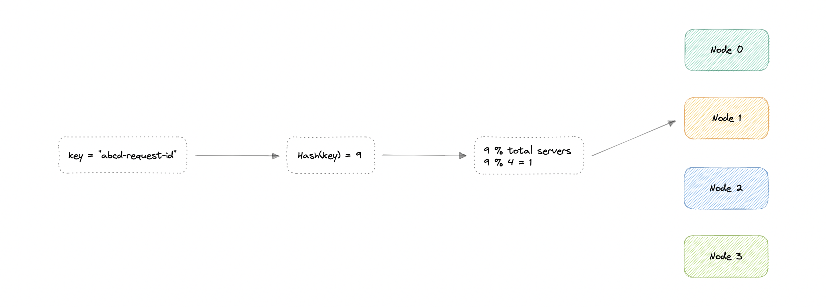
Where,
key: Request ID or IP.
H: Hash function result.
N: Total number of nodes.
Node: The node where the request will be routed.
The problem with this is if we add or remove a node, it will cause N to change, meaning our mapping strategy will break as the same requests will now map to a different server. As a consequence, the majority of requests will need to be redistributed which is very inefficient.
We want to uniformly distribute requests among different nodes such that we should be able to add or remove nodes with minimal effort. Hence, we need a distribution scheme that does not depend directly on the number of nodes (or servers), so that, when adding or removing nodes, the number of keys that need to be relocated is minimized.
Consistent hashing solves this horizontal scalability problem by ensuring that every time we scale up or down, we do not have to re-arrange all the keys or touch all the servers.
Now that we understand the problem, let’s discuss consistent hashing in detail.
How does it work
Consistent Hashing is a distributed hashing scheme that operates independently of the number of nodes in a distributed hash table by assigning them a position on an abstract circle, or hash ring. This allows servers and objects to scale without affecting the overall system.
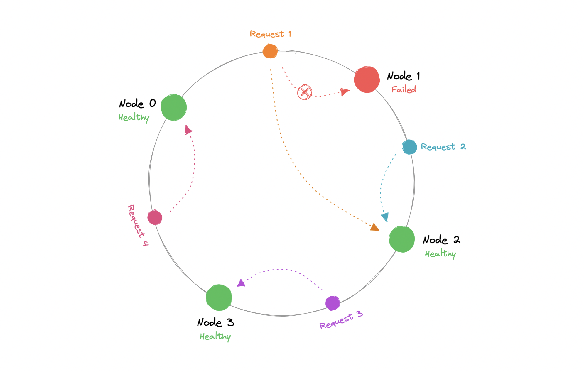
Using consistent hashing, only K/N data would require re-distributing.
Where,
R: Data that would require re-distribution.
K: Number of partition keys.
N: Number of nodes.
The output of the hash function is a range let’s say 0...m-1 which we can represent on our hash ring. We hash the requests and distribute them on the ring depending on what the output was. Similarly, we also hash the node and distribute them on the same ring as well.
Where,
key: Request/Node ID or IP.
P: Position on the hash ring.
m: Total range of the hash ring.
Now, when the request comes in we can simply route it to the closest node in a clockwise (can be counterclockwise as well) manner. This means that if a new node is added or removed, we can use the nearest node and only a fraction of the requests need to be re-routed.
In theory, consistent hashing should distribute the load evenly however it doesn’t happen in practice. Usually, the load distribution is uneven and one server may end up handling the majority of the request becoming a hotspot, essentially a bottleneck for the system. We can fix this by adding extra nodes but that can be expensive.
Let’s see how we can address these issues.
Virtual Nodes
In order to ensure a more evenly distributed load, we can introduce the idea of a virtual node, sometimes also referred to as a VNode.
Instead of assigning a single position to a node, the hash range is divided into multiple smaller ranges, and each physical node is assigned several of these smaller ranges. Each of these subranges is considered a VNode. Hence, virtual nodes are basically existing physical nodes mapped multiple times across the hash ring to minimize changes to a node’s assigned range.
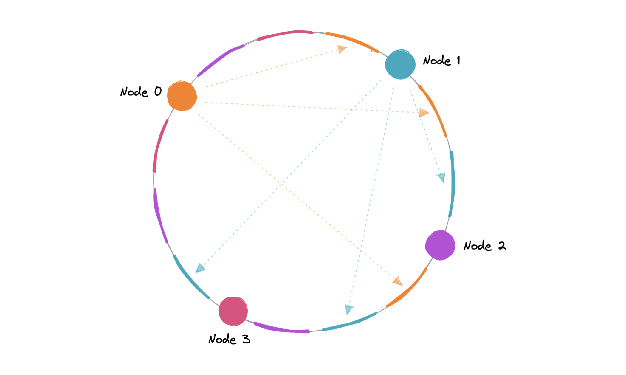
For this, we can use k number of hash functions.
Where,
key: Request/Node ID or IP.
k: Number of hash functions.
P: Position on the hash ring.
m: Total range of the hash ring.
As VNodes help spread the load more evenly across the physical nodes on the cluster by diving the hash ranges into smaller subranges, this speeds up the re-balancing process after adding or removing nodes. This also helps us reduce the probability of hotspots.
Data Replication
To ensure high availability and durability, consistent hashing replicates each data item on multiple N nodes in the system where the value N is equivalent to the replication factor.
The replication factor is the number of nodes that will receive the copy of the same data. In eventually consistent systems, this is done asynchronously.
Advantages
Let’s look at some advantages of consistent hashing:
- Makes rapid scaling up and down more predictable.
- Facilitates partitioning and replication across nodes.
- Enables scalability and availability.
- Reduces hotspots.
Disadvantages
Below are some disadvantages of consistent hashing:
- Increases complexity.
- Cascading failures.
- Load distribution can still be uneven.
- Key management can be expensive when nodes transiently fail.
Examples
Let’s look at some examples where consistent hashing is used:
- Data partitioning in Apache Cassandra.
- Load distribution across multiple storage hosts in Amazon DynamoDB.
Database Federation
Federation (or functional partitioning) splits up databases by function. The federation architecture makes several distinct physical databases appear as one logical database to end-users.
All of the components in a federation are tied together by one or more federal schemas that express the commonality of data throughout the federation. These federated schemas are used to specify the information that can be shared by the federation components and to provide a common basis for communication among them.
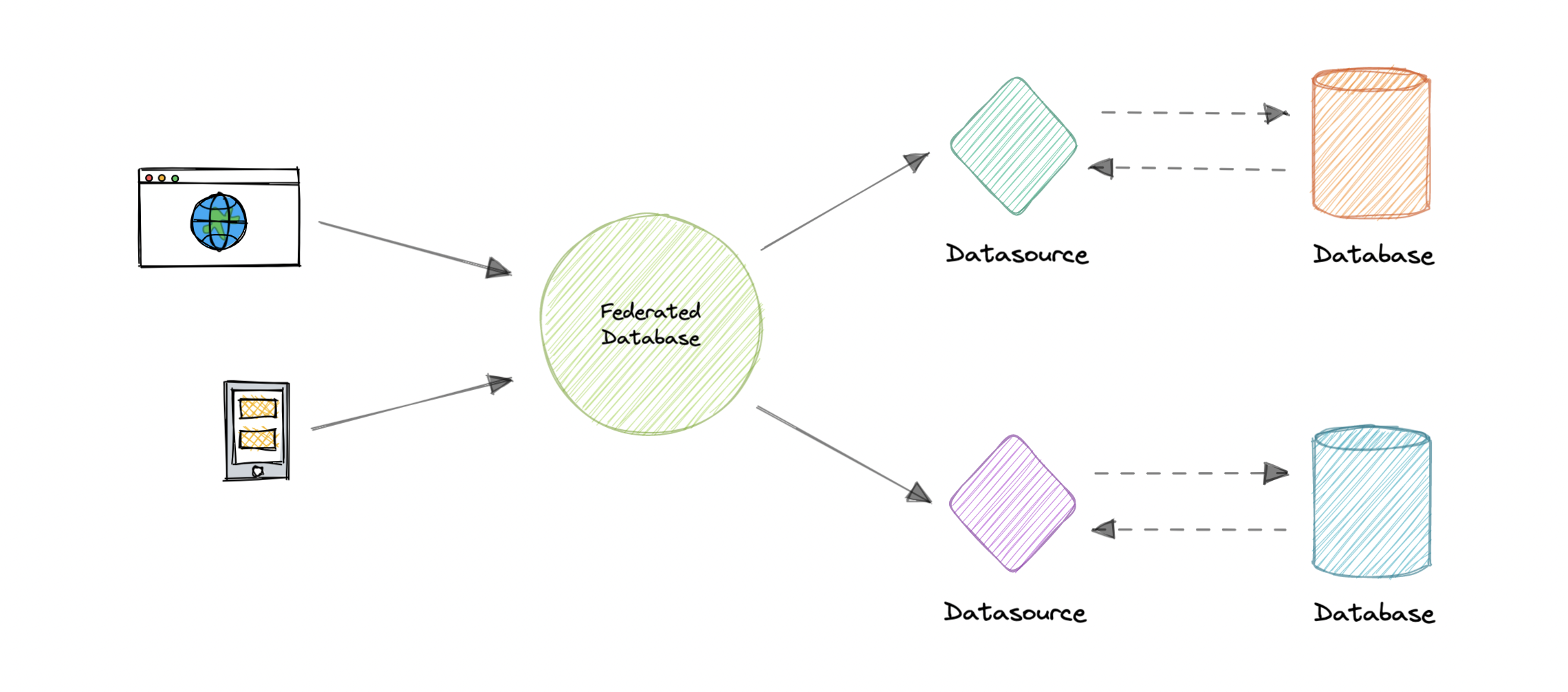
Federation also provides a cohesive, unified view of data derived from multiple sources. The data sources for federated systems can include databases and various other forms of structured and unstructured data.
Characteristics
Let’s look at some key characteristics of a federated database:
- Transparency: Federated database masks user differences and implementations of underlying data sources. Therefore, the users do not need to be aware of where the data is stored.
- Heterogeneity: Data sources can differ in many ways. A federated database system can handle different hardware, network protocols, data models, etc.
- Extensibility: New sources may be needed to meet the changing needs of the business. A good federated database system needs to make it easy to add new sources.
- Autonomy: A Federated database does not change existing data sources, interfaces should remain the same.
- Data integration: A federated database can integrate data from different protocols, database management systems, etc.
Advantages
Here are some advantages of federated databases:
- Flexible data sharing.
- Autonomy among the database components.
- Access heterogeneous data in a unified way.
- No tight coupling of applications with legacy databases.
Disadvantages
Below are some disadvantages of federated databases:
- Adds more hardware and additional complexity.
- Joining data from two databases is complex.
- Dependence on autonomous data sources.
- Query performance and scalability.
N-tier architecture
N-tier architecture divides an application into logical layers and physical tiers. Layers are a way to separate responsibilities and manage dependencies. Each layer has a specific responsibility. A higher layer can use services in a lower layer, but not the other way around.

Tiers are physically separated, running on separate machines. A tier can call to another tier directly, or use asynchronous messaging. Although each layer might be hosted in its own tier, that’s not required. Several layers might be hosted on the same tier. Physically separating the tiers improves scalability and resiliency and adds latency from the additional network communication.
An N-tier architecture can be of two types:
- In a closed layer architecture, a layer can only call the next layer immediately down.
- In an open layer architecture, a layer can call any of the layers below it.
A closed-layer architecture limits the dependencies between layers. However, it might create unnecessary network traffic, if one layer simply passes requests along to the next layer.
Types of N-Tier architectures
Let’s look at some examples of N-Tier architecture:
3-Tier architecture
3-Tier is widely used and consists of the following different layers:
- Presentation layer: Handles user interactions with the application.
- Business Logic layer: Accepts the data from the application layer, validates it as per business logic and passes it to the data layer.
- Data Access layer: Receives the data from the business layer and performs the necessary operation on the database.
2-Tier architecture
In this architecture, the presentation layer runs on the client and communicates with a data store. There is no business logic layer or immediate layer between client and server.
Single Tier or 1-Tier architecture
It is the simplest one as it is equivalent to running the application on a personal computer. All of the required components for an application to run are on a single application or server.
Advantages
Here are some advantages of using N-tier architecture:
- Can improve availability.
- Better security as layers can behave like a firewall.
- Separate tiers allow us to scale them as needed.
- Improve maintenance as different people can manage different tiers.
Disadvantages
Below are some disadvantages of N-tier architecture:
- Increased complexity of the system as a whole.
- Increased network latency as the number of tiers increases.
- Expensive as every tier will have its own hardware cost.
- Difficult to manage network security.
Message Brokers
A message broker is a software that enables applications, systems, and services to communicate with each other and exchange information. The message broker does this by translating messages between formal messaging protocols. This allows interdependent services to “talk” with one another directly, even if they were written in different languages or implemented on different platforms.

Message brokers can validate, store, route, and deliver messages to the appropriate destinations. They serve as intermediaries between other applications, allowing senders to issue messages without knowing where the receivers are, whether or not they are active, or how many of them there are. This facilitates the decoupling of processes and services within systems.
Models
Message brokers offer two basic message distribution patterns or messaging styles:
- Point-to-Point messaging: This is the distribution pattern utilized in message queues with a one-to-one relationship between the message’s sender and receiver.
- Publish-subscribe messaging: In this message distribution pattern, often referred to as “pub/sub”, the producer of each message publishes it to a topic, and multiple message consumers subscribe to topics from which they want to receive messages.
We will discuss these messaging patterns in detail in the later tutorials.
Message brokers vs Event streaming
Message brokers can support two or more messaging patterns, including message queues and pub/sub, while event streaming platforms only offer pub/sub-style distribution patterns. Designed for use with high volumes of messages, event streaming platforms are readily scalable. They’re capable of ordering streams of records into categories called topics and storing them for a predetermined amount of time. Unlike message brokers, however, event streaming platforms cannot guarantee message delivery or track which consumers have received the messages.
Event streaming platforms offer more scalability than message brokers but fewer features that ensure fault tolerance like message resending, as well as more limited message routing and queueing capabilities.
Message brokers vs Enterprise Service Bus (ESB)
Enterprise Service Bus (ESB) infrastructure is complex and can be challenging to integrate and expensive to maintain. It’s difficult to troubleshoot them when problems occur in production environments, they’re not easy to scale, and updating is tedious.
Whereas message brokers are a “lightweight” alternative to ESBs that provide similar functionality, a mechanism for inter-service communication, at a lower cost. They’re well-suited for use in the microservices architectures that have become more prevalent as ESBs have fallen out of favor.
Examples
Here are some commonly used message brokers:
Message Queues
A message queue is a form of service-to-service communication that facilitates asynchronous communication. It asynchronously receives messages from producers and sends them to consumers.
Queues are used to effectively manage requests in large-scale distributed systems. In small systems with minimal processing loads and small databases, writes can be predictably fast. However, in more complex and large systems writes can take an almost non-deterministic amount of time.

Working
Messages are stored in the queue until they are processed and deleted. Each message is processed only once by a single consumer. Here’s how it works:
- A producer publishes a job to the queue, then notifies the user of the job status.
- A consumer picks up the job from the queue, processes it, then signals that the job is complete.
Advantages
Let’s discuss some advantages of using a message queue:
- Scalability: Message queues make it possible to scale precisely where we need to. When workloads peak, multiple instances of our application can all add requests to the queue without the risk of collision
- Decoupling: Message queues remove dependencies between components and significantly simplify the implementation of decoupled applications.
- Performance: Message queues enable asynchronous communication, which means that the endpoints that are producing and consuming messages interact with the queue, not each other. Producers can add requests to the queue without waiting for them to be processed.
- Reliability: Queues make our data persistent, and reduce the errors that happen when different parts of our system go offline.
Features
Now, let’s discuss some desired features of message queues:
Push or Pull Delivery
Most message queues provide both push and pull options for retrieving messages. Pull means continuously querying the queue for new messages. Push means that a consumer is notified when a message is available. We can also use long-polling to allow pulls to wait a specified amount of time for new messages to arrive.
FIFO (First-In-First-Out) Queues
In these queues, the oldest (or first) entry, sometimes called the “head” of the queue, is processed first.
Schedule or Delay Delivery
Many message queues support setting a specific delivery time for a message. If we need to have a common delay for all messages, we can set up a delay queue.
At-Least-Once Delivery
Message queues may store multiple copies of messages for redundancy and high availability, and resend messages in the event of communication failures or errors to ensure they are delivered at least once.
Exactly-Once Delivery
When duplicates can’t be tolerated, FIFO (first-in-first-out) message queues will make sure that each message is delivered exactly once (and only once) by filtering out duplicates automatically.
Dead-letter Queues
A dead-letter queue is a queue to which other queues can send messages that can’t be processed successfully. This makes it easy to set them aside for further inspection without blocking the queue processing or spending CPU cycles on a message that might never be consumed successfully.
Ordering
Most message queues provide best-effort ordering which ensures that messages are generally delivered in the same order as they’re sent and that a message is delivered at least once.
Poison-pill Messages
Poison pills are special messages that can be received, but not processed. They are a mechanism used in order to signal a consumer to end its work so it is no longer waiting for new inputs, and are similar to closing a socket in a client/server model.
Security
Message queues will authenticate applications that try to access the queue, this allows us to encrypt messages over the network as well as in the queue itself.
Task Queues
Tasks queues receive tasks and their related data, run them, then deliver their results. They can support scheduling and can be used to run computationally-intensive jobs in the background.
Backpressure
If queues start to grow significantly, the queue size can become larger than memory, resulting in cache misses, disk reads, and even slower performance. Backpressure can help by limiting the queue size, thereby maintaining a high throughput rate and good response times for jobs already in the queue. Once the queue fills up, clients get a server busy or HTTP 503 status code to try again later. Clients can retry the request at a later time, perhaps with exponential backoff strategy.
Examples
Following are some widely used message queues:
Publish-Subscribe
Similar to a message queue, publish-subscribe is also a form of service-to-service communication that facilitates asynchronous communication. In a pub/sub model, any message published to a topic is pushed immediately to all the subscribers of the topic.
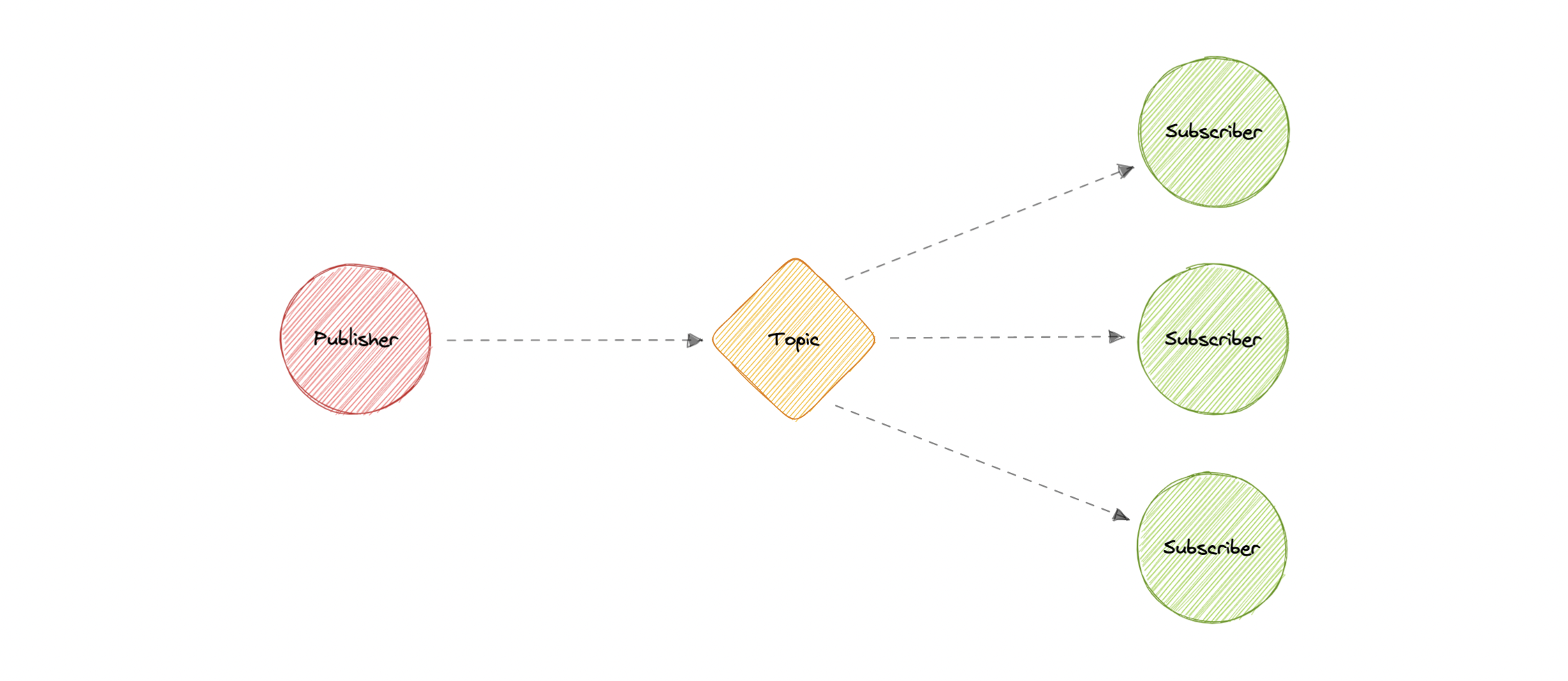
The subscribers to the message topic often perform different functions, and can each do something different with the message in parallel. The publisher doesn’t need to know who is using the information that it is broadcasting, and the subscribers don’t need to know where the message comes from. This style of messaging is a bit different than message queues, where the component that sends the message often knows the destination it is sending to.
Working
Unlike message queues, which batch messages until they are retrieved, message topics transfer messages with little or no queuing and push them out immediately to all subscribers. Here’s how it works:
- A message topic provides a lightweight mechanism to broadcast asynchronous event notifications and endpoints that allow software components to connect to the topic in order to send and receive those messages.
- To broadcast a message, a component called a publisher simply pushes a message to the topic.
- All components that subscribe to the topic (known as subscribers) will receive every message that was broadcasted.
Advantages
Let’s discuss some advantages of using publish-subscribe:
- Eliminate Polling: Message topics allow instantaneous, push-based delivery, eliminating the need for message consumers to periodically check or “poll” for new information and updates. This promotes faster response time and reduces the delivery latency which can be particularly problematic in systems where delays cannot be tolerated.
- Dynamic Targeting: Pub/Sub makes the discovery of services easier, more natural, and less error-prone. Instead of maintaining a roster of peers where an application can send messages, a publisher will simply post messages to a topic. Then, any interested party will subscribe its endpoint to the topic, and start receiving these messages. Subscribers can change, upgrade, multiply or disappear and the system dynamically adjusts.
- Decoupled and Independent Scaling: Publishers and subscribers are decoupled and work independently from each other, which allows us to develop and scale them independently.
- Simplify Communication: The Publish-Subscribe model reduces complexity by removing all the point-to-point connections with a single connection to a message topic, which will manage subscriptions and decide what messages should be delivered to which endpoints.
Features
Now, let’s discuss some desired features of publish-subscribe:
Push Delivery
Pub/Sub messaging instantly pushes asynchronous event notifications when messages are published to the message topic. Subscribers are notified when a message is available.
Multiple Delivery Protocols
In the Publish-Subscribe model, topics can typically connect to multiple types of endpoints, such as message queues, serverless functions, HTTP servers, etc.
Fanout
This scenario happens when a message is sent to a topic and then replicated and pushed to multiple endpoints. Fanout provides asynchronous event notifications which in turn allows for parallel processing.
Filtering
This feature empowers the subscriber to create a message filtering policy so that it will only get the notifications it is interested in, as opposed to receiving every single message posted to the topic.
Durability
Pub/Sub messaging services often provide very high durability, and at least once delivery, by storing copies of the same message on multiple servers.
Security
Message topics authenticate applications that try to publish content, this allows us to use encrypted endpoints and encrypt messages in transit over the network.
Examples
Here are some commonly used publish-subscribe technologies:
Enterprise Service Bus (ESB)
An Enterprise Service Bus (ESB) is an architectural pattern whereby a centralized software component performs integrations between applications. It performs transformations of data models, handles connectivity, performs message routing, converts communication protocols, and potentially manages the composition of multiple requests. The ESB can make these integrations and transformations available as a service interface for reuse by new applications.
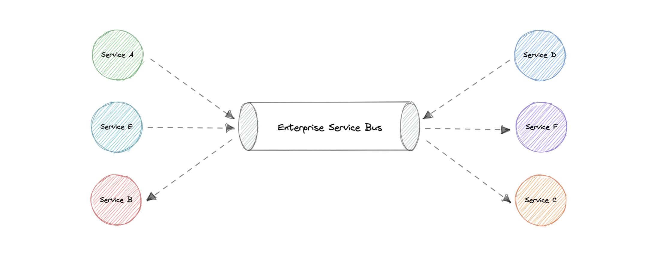
Advantages
In theory, a centralized ESB offers the potential to standardize and dramatically simplify communication, messaging, and integration between services across the enterprise. Here are some advantages of using an ESB:
- Improved developer productivity: Enables developers to incorporate new technologies into one part of an application without touching the rest of the application.
- Simpler, more cost-effective scalability: Components can be scaled independently of others.
- Greater resilience: Failure of one component does not impact the others, and each microservice can adhere to its own availability requirements without risking the availability of other components in the system.
Disadvantages
While ESBs were deployed successfully in many organizations, in many other organizations the ESB came to be seen as a bottleneck. Here are some disadvantages of using an ESB:
- Making changes or enhancements to one integration could destabilize others who use that same integration.
- A single point of failure can bring down all communications.
- Updates to the ESB often impact existing integrations, so there is significant testing required to perform any update.
- ESB is centrally managed which makes cross-team collaboration challenging.
- High configuration and maintenance complexity.
Examples
Below are some widely used Enterprise Service Bus (ESB) technologies:
Monoliths and Microservices
Monoliths
A monolith is a self-contained and independent application. It is built as a single unit and is responsible for not just a particular task, but can perform every step needed to satisfy a business need.
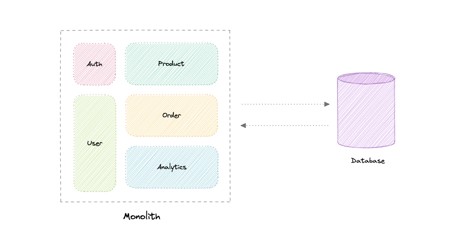
Advantages
Following are some advantages of monoliths:
- Simple to develop or debug.
- Fast and reliable communication.
- Easy monitoring and testing.
- Supports ACID transactions.
Disadvantages
Some common disadvantages of monoliths are:
- Maintenance becomes hard as the codebase grows.
- Tightly coupled application, hard to extend.
- Requires commitment to a particular technology stack.
- On each update, the entire application is redeployed.
- Reduced reliability as a single bug can bring down the entire system.
- Difficult to scale or adopt technologies new technologies.
Modular Monoliths
A Modular Monolith is an approach where we build and deploy a single application (that’s the Monolith part), but we build it in a way that breaks up the code into independent modules for each of the features needed in our application.
This approach reduces the dependencies of a module in such as way that we can enhance or change a module without affecting other modules. When done right, this can be really beneficial in the long term as it reduces the complexity that comes with maintaining a monolith as the system grows.
Microservices
A microservices architecture consists of a collection of small, autonomous services where each service is self-contained and should implement a single business capability within a bounded context. A bounded context is a natural division of business logic that provides an explicit boundary within which a domain model exists.
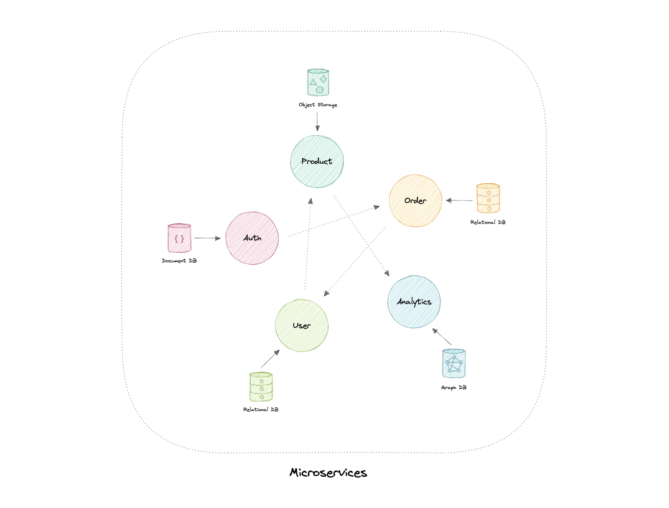
Each service has a separate codebase, which can be managed by a small development team. Services can be deployed independently and a team can update an existing service without rebuilding and redeploying the entire application.
Services are responsible for persisting their own data or external state (database per service). This differs from the traditional model, where a separate data layer handles data persistence.
Characteristics
The microservices architecture style has the following characteristics:
- Loosely coupled: Services should be loosely coupled so that they can be independently deployed and scaled. This will lead to the decentralization of development teams and thus, enabling them to develop and deploy faster with minimal constraints and operational dependencies.
- Small but focused: It’s about scope and responsibilities and not size, a service should be focused on a specific problem. Basically, “It does one thing and does it well”. Ideally, they can be independent of the underlying architecture.
- Built for businesses: The microservices architecture is usually organized around business capabilities and priorities.
- Resilience & Fault tolerance: Services should be designed in such a way that they still function in case of failure or errors. In environments with independently deployable services, failure tolerance is of the highest importance.
- Highly maintainable: Service should be easy to maintainable and test because services that cannot be maintained will be re-written.
Advantages
Here are some advantages of microservices architecture:
- Loosely coupled services.
- Services can be deployed independently.
- Highly agile for multiple development teams.
- Improves fault tolerance and data isolation.
- Better scalability as each service can be scaled independently.
- Eliminates any long-term commitment to a particular technology stack.
Disadvantages
Microservices architecture brings its own set of challenges:
- Complexity of a distributed system.
- Testing is more difficult.
- Expensive to maintain (individual servers, databases, etc.).
- Inter-service communication has its own challenges.
- Data integrity and consistency.
- Network congestion and latency.
Best practices
Let’s discuss some microservices best practices:
- Model services around the business domain.
- Services should have loose coupling and high functional cohesion.
- Isolate failures and use resiliency strategies to prevent failures within a service from cascading.
- Services should only communicate through well-designed APIs. Avoid leaking implementation details.
- Data storage should be private to the service that owns the data
- Avoid coupling between services. Causes of coupling include shared database schemas and rigid communication protocols.
- Decentralize everything. Individual teams are responsible for designing and building services. Avoid sharing code or data schemas.
- Fail fast by using a circuit breaker to achieve fault tolerance.
- Ensure that the API changes are backward compatible.
Pitfalls
Below are some common pitfalls of microservices architecture:
- Service boundaries are not based on the business domain.
- Underestimating how hard is to build a distributed system.
- Shared database or common dependencies between services.
- Lack of Business Alignment.
- Lack of clear ownership.
- Lack of idempotency.
- Trying to do everything ACID instead of BASE.
- Lack of design for fault tolerance may result in cascading failures.
Beware of the distributed monolith
Distributed Monolith is a system that resembles the microservices architecture but is tightly coupled within itself like a monolithic application. Adopting microservices architecture comes with a lot of advantages. But while making one, there are good chances that we might end up with a distributed monolith.
Our microservices are just a distributed monolith if any of these apply to it:
- Requires low latency communication.
- Services don’t scale easily.
- Dependency between services.
- Sharing the same resources such as databases.
- Tightly coupled systems.
One of the primary reasons to build an application using microservices architecture is to have scalability. Therefore, microservices should have loosely coupled services which enable every service to be independent. The distributed monolith architecture takes this away and causes most components to depend on one another, increasing design complexity.
Microservices vs Service-oriented architecture (SOA)
You might have seen Service-oriented architecture (SOA) mentioned around the internet, sometimes even interchangeably with microservices, but they are different from each other and the main distinction between the two approaches comes down to scope.
Service-oriented architecture (SOA) defines a way to make software components reusable via service interfaces. These interfaces utilize common communication standards and focus on maximizing application service reusability whereas microservices are built as a collection of various smallest independent service units focused on team autonomy and decoupling.
Why you don’t need microservices

So, you might be wondering, monoliths seem like a bad idea to begin with, why would anyone use that?
Well, it depends. While each approach has its own advantages and disadvantages, it is advised to start with a monolith when building a new system. It is important to understand, that microservices are not a silver bullet instead they solve an organizational problem. Microservices architecture is about your organizational priorities and team as much as it’s about technology.
Before making the decision to move to microservices architecture, you need to ask yourself questions like:
- “Is the team too large to work effectively on a shared codebase?”
- “Are teams blocked on other teams?”
- “Does microservices deliver clear business value for us?”
- “Is my business mature enough to use microservices?”
- “Is our current architecture limiting us with communication overhead?”
If your application does not require to be broken down into microservices, you don’t need this. There is no absolute necessity that all applications should be broken down into microservices.
We frequently draw inspiration from companies such as Netflix and their use of microservices, but we overlook the fact that we are not Netflix. They went through a lot of iterations and models before they had a market-ready solution, and this architecture became acceptable for them when they identified and solved the problem they were trying to tackle.
That’s why it’s essential to understand in-depth if your business actually needs microservices. What I’m trying to say is microservices are solutions to complex concerns and if your business doesn’t have complex issues, you don’t need them.
Event-Driven Architecture (EDA)
Event-Driven Architecture (EDA) is about using events as a way to communicate within a system. Generally, leveraging a message broker to publish and consume events asynchronously. The publisher is unaware of who is consuming an event and the consumers are unaware of each other. Event-Driven Architecture is simply a way of achieving loose coupling between services within a system.
What is an event?
An event is a data point that represents state changes in a system. It doesn’t specify what should happen and how the change should modify the system, it only notifies the system of a particular state change. When a user makes an action, they trigger an event.
Components
Event-driven architectures have three key components:
- Event producers: Publishes an event to the router.
- Event routers: Filters and pushes the events to consumers.
- Event consumers: Uses events to reflect changes in the system.
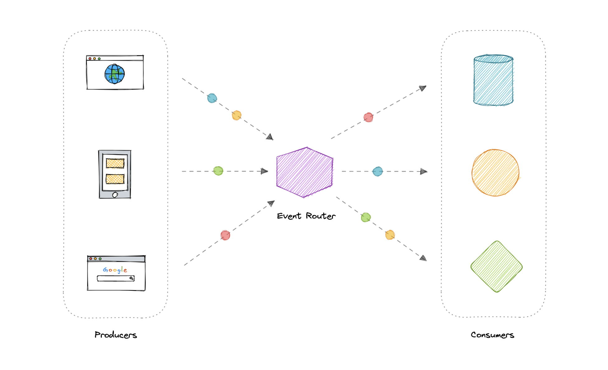
Note: Dots in the diagram represents different events in the system.
Patterns
There are several ways to implement the event-driven architecture, and which method we use depends on the use case but here are some common examples:
Note: Each of these methods is discussed separately.
Advantages
Let’s discuss some advantages:
- Decoupled producers and consumers.
- Highly scalable and distributed.
- Easy to add new consumers.
- Improves agility.
Challenges
Here are some challenges of event-drive architecture:
- Guaranteed delivery.
- Error handling is difficult.
- Event-driven systems are complex in general.
- Exactly once, in-order processing of events.
Use cases
Below are some common use cases where event-driven architectures are beneficial:
- Metadata and metrics.
- Server and security logs.
- Integrating heterogeneous systems.
- Fanout and parallel processing.
Examples
Here are some widely used technologies for implementing event-driven architectures:
Event Sourcing
Instead of storing just the current state of the data in a domain, use an append-only store to record the full series of actions taken on that data. The store acts as the system of record and can be used to materialize the domain objects.
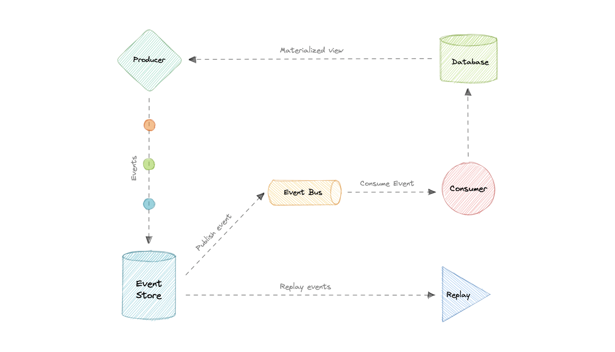
This can simplify tasks in complex domains, by avoiding the need to synchronize the data model and the business domain, while improving performance, scalability, and responsiveness. It can also provide consistency for transactional data, and maintain full audit trails and history that can enable compensating actions.
Event sourcing vs Event-Driven Architecture (EDA)
Event sourcing is seemingly constantly being confused with Event-driven Architecture (EDA). Event-driven architecture is about using events to communicate between service boundaries. Generally, leveraging a message broker to publish and consume events asynchronously within other boundaries.
Whereas, event sourcing is about using events as a state, which is a different approach to storing data. Rather than storing the current state, we’re instead going to be storing events. Also, event sourcing is one of the several patterns to implement an event-driven architecture.
Advantages
Let’s discuss some advantages of using event sourcing:
- Excellent for real-time data reporting.
- Great for fail-safety, data can be reconstituted from the event store.
- Extremely flexible, any type of message can be stored.
- Preferred way of achieving audit logs functionality for high compliance systems.
Disadvantages
Following are the disadvantages of event sourcing:
- Requires an extremely efficient network infrastructure.
- Requires a reliable way to control message formats, such as a schema registry.
- Different events will contain different payloads.
Command and Query Responsibility Segregation (CQRS)
Command Query Responsibility Segregation (CQRS) is an architectural pattern that divides a system’s actions into commands and queries. It was first described by Greg Young.
In CQRS, a command is an instruction, a directive to perform a specific task. It is an intention to change something and doesn’t return a value, only an indication of success or failure. And, a query is a request for information that doesn’t change the system’s state or cause any side effects.
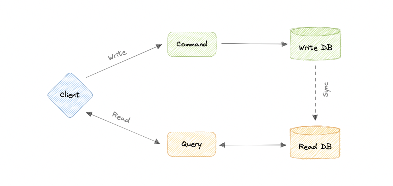
The core principle of CQRS is the separation of commands and queries. They perform fundamentally different roles within a system, and separating them means that each can be optimized as needed, which distributed systems can really benefit from.
CQRS with Event Sourcing
The CQRS pattern is often used along with the Event Sourcing pattern. CQRS-based systems use separate read and write data models, each tailored to relevant tasks and often located in physically separate stores.
When used with the Event Sourcing pattern, the store of events is the write model and is the official source of information. The read model of a CQRS-based system provides materialized views of the data, typically as highly denormalized views.
Advantages
Let’s discuss some advantages of CQRS:
- Allows independent scaling of read and write workloads.
- Easier scaling, optimizations, and architectural changes.
- Closer to business logic with loose coupling.
- The application can avoid complex joins when querying.
- Clear boundaries between the system behavior.
Disadvantages
Below are some disadvantages of CQRS:
- More complex application design.
- Message failures or duplicate messages can occur.
- Dealing with eventual consistency is a challenge.
- Increased system maintenance efforts.
Use cases
Here are some scenarios where CQRS will be helpful:
- The performance of data reads must be fine-tuned separately from the performance of data writes.
- The system is expected to evolve over time and might contain multiple versions of the model, or where business rules change regularly.
- Integration with other systems, especially in combination with event sourcing, where the temporal failure of one subsystem shouldn’t affect the availability of the others.
- Better security to ensure that only the right domain entities are performing writes on the data.
API Gateway
The API Gateway is an API management tool that sits between a client and a collection of backend services. It is a single entry point into a system that encapsulates the internal system architecture and provides an API that is tailored to each client. It also has other responsibilities such as authentication, monitoring, load balancing, caching, throttling, logging, etc.
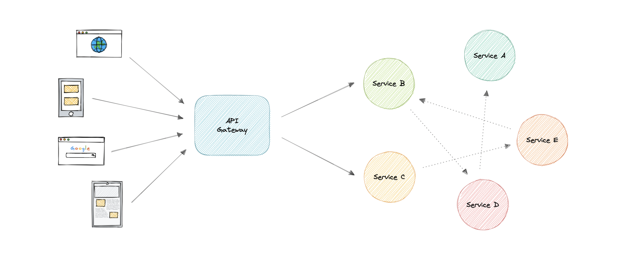
Why do we need an API Gateway?
The granularity of APIs provided by microservices is often different than what a client needs. Microservices typically provide fine-grained APIs, which means that clients need to interact with multiple services. Hence, an API gateway can provide a single entry point for all clients with some additional features and better management.
Features
Below are some desired features of an API Gateway:
- Authentication and Authorization
- Service discovery
- Reverse Proxy
- Caching
- Security
- Retry and Circuit breaking
- Load balancing
- Logging, Tracing
- API composition
- Rate limiting and throttling
- Versioning
- Routing
- IP whitelisting or blacklisting
Advantages
Let’s look at some advantages of using an API Gateway:
- Encapsulates the internal structure of an API.
- Provides a centralized view of the API.
- Simplifies the client code.
- Monitoring, analytics, tracing, and other such features.
Disadvantages
Here are some possible disadvantages of an API Gateway:
- Possible single point of failure.
- Might impact performance.
- Can become a bottleneck if not scaled properly.
- Configuration can be challenging.
Backend For Frontend (BFF) pattern
In the Backend For Frontend (BFF) pattern, we create separate backend services to be consumed by specific frontend applications or interfaces. This pattern is useful when we want to avoid customizing a single backend for multiple interfaces. This pattern was first described by Sam Newman.
Also, sometimes the output of data returned by the microservices to the front end is not in the exact format or filtered as needed by the front end. To solve this issue, the frontend should have some logic to reformat the data, and therefore, we can use BFF to shift some of this logic to the intermediate layer.
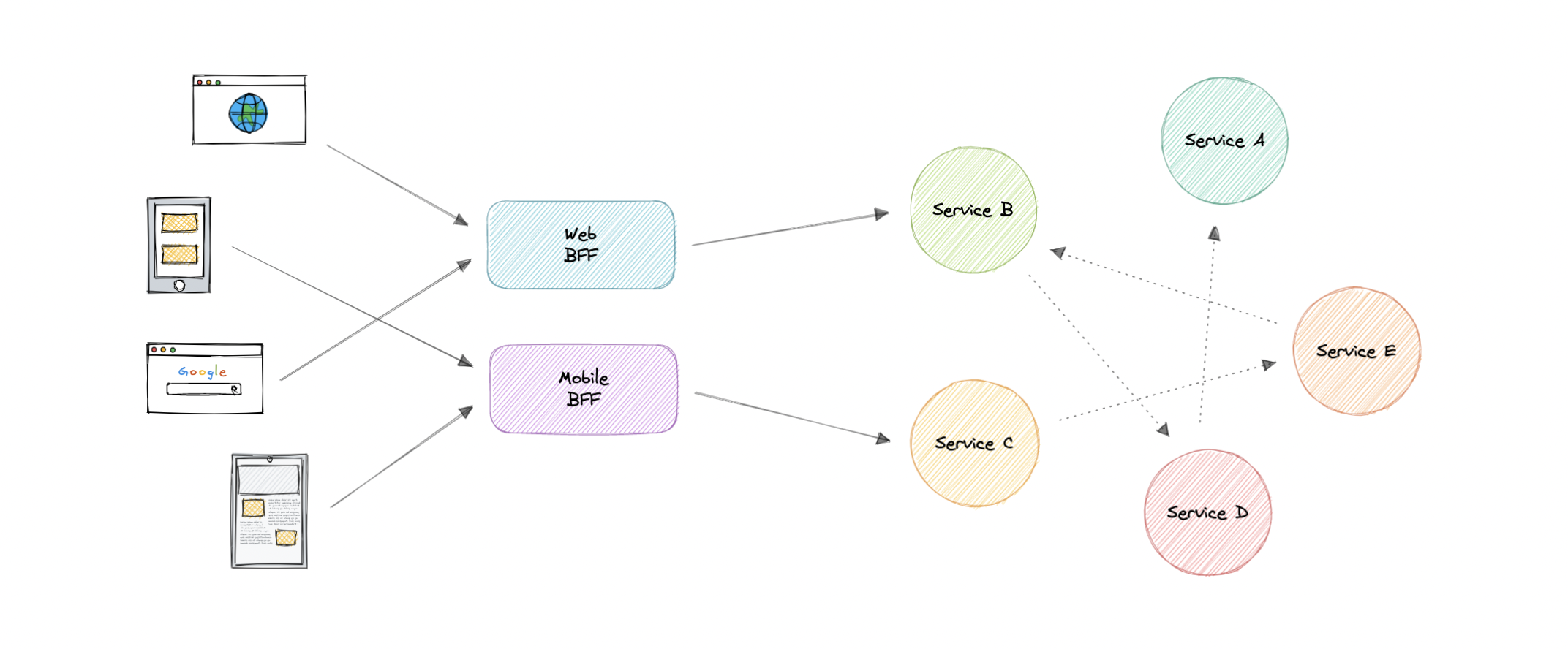
The primary function of the backend for the frontend pattern is to get the required data from the appropriate service, format the data, and sent it to the frontend.
GraphQL performs really well as a backend for frontend (BFF).
When to use this pattern?
We should consider using a Backend For Frontend (BFF) pattern when:
- A shared or general purpose backend service must be maintained with significant development overhead.
- We want to optimize the backend for the requirements of a specific client.
- Customizations are made to a general-purpose backend to accommodate multiple interfaces.
Examples
Following are some widely used gateways technologies:
REST, GraphQL, gRPC
A good API design is always a crucial part of any system. But it is also important to pick the right API technology. So, in this tutorial, we will briefly discuss different API technologies such as REST, GraphQL, and gRPC.
What’s an API?
Before we even get into API technologies, let’s first understand what is an API.
An API is a set of definitions and protocols for building and integrating application software. It’s sometimes referred to as a contract between an information provider and an information user establishing the content required from the producer and the content required by the consumer.
In other words, if you want to interact with a computer or system to retrieve information or perform a function, an API helps you communicate what you want to that system so it can understand and complete the request.
REST
A REST API (also known as RESTful API) is an application programming interface that conforms to the constraints of REST architectural style and allows for interaction with RESTful web services. REST stands for Representational State Transfer and it was first introduced by Roy Fielding in the year 2000.
In REST API, the fundamental unit is a resource.
Concepts
Let’s discuss some concepts of a RESTful API.
Constraints
In order for an API to be considered RESTful, it has to conform to these architectural constraints:
- Uniform Interface: There should be a uniform way of interacting with a given server.
- Client-Server: A client-server architecture managed through HTTP.
- Stateless: No client context shall be stored on the server between requests.
- Cacheable: Every response should include whether the response is cacheable or not and for how much duration responses can be cached at the client-side.
- Layered system: An application architecture needs to be composed of multiple layers.
- Code on demand: Return executable code to support a part of your application. (optional)
HTTP Verbs
HTTP defines a set of request methods to indicate the desired action to be performed for a given resource. Although they can also be nouns, these request methods are sometimes referred to as HTTP verbs. Each of them implements a different semantic, but some common features are shared by a group of them.
Below are some commonly used HTTP verbs:
- GET: Request a representation of the specified resource.
- HEAD: Response is identical to a
GETrequest, but without the response body. - POST: Submits an entity to the specified resource, often causing a change in state or side effects on the server.
- PUT: Replaces all current representations of the target resource with the request payload.
- DELETE: Deletes the specified resource.
- PATCH: Applies partial modifications to a resource.
HTTP response codes
HTTP response status codes indicate whether a specific HTTP request has been successfully completed.
There are five classes defined by the standard:
- 1xx - Informational responses.
- 2xx - Successful responses.
- 3xx - Redirection responses.
- 4xx - Client error responses.
- 5xx - Server error responses.
For example, HTTP 200 means that the request was successful.
Advantages
Let’s discuss some advantages of REST API:
- Simple and easy to understand.
- Flexible and portable.
- Good caching support.
- Client and server are decoupled.
Disadvantages
Let’s discuss some disadvantages of REST API:
- Over-fetching of data.
- Sometimes multiple round trips to the server are required.
Use cases
REST APIs are pretty much used universally and are the default standard for designing APIs. Overall REST APIs are quite flexible and can fit almost all scenarios.
Example
Here’s an example usage of a REST API that operates on a users resource.
| URI | HTTP verb | Description |
|---|---|---|
| /users | GET | Get all users |
| /users/{id} | GET | Get a user by id |
| /users | POST | Add a new user |
| /users/{id} | PATCH | Update a user by id |
| /users/{id} | DELETE | Delete a user by id |
There is so much more to learn when it comes to REST APIs, I will highly recommend looking into Hypermedia as the Engine of Application State (HATEOAS).
GraphQL
GraphQL is a query language and server-side runtime for APIs that prioritizes giving clients exactly the data they request and no more. It was developed by Facebook and later open-sourced in 2015.
GraphQL is designed to make APIs fast, flexible, and developer-friendly. Additionally, GraphQL gives API maintainers the flexibility to add or deprecate fields without impacting existing queries. Developers can build APIs with whatever methods they prefer, and the GraphQL specification will ensure they function in predictable ways to clients.
In GraphQL, the fundamental unit is a query.
Concepts
Let’s briefly discuss some key concepts in GraphQL:
Schema
A GraphQL schema describes the functionality clients can utilize once they connect to the GraphQL server.
Queries
A query is a request made by the client. It can consist of fields and arguments for the query. The operation type of a query can also be a mutation which provides a way to modify server-side data.
Resolvers
Resolver is a collection of functions that generate responses for a GraphQL query. In simple terms, a resolver acts as a GraphQL query handler.
Advantages
Let’s discuss some advantages of GraphQL:
- Eliminates over-fetching of data.
- Strongly defined schema.
- Code generation support.
- Payload optimization.
Disadvantages
Let’s discuss some disadvantages of GraphQL:
- Shifts complexity to server-side.
- Caching becomes hard.
- Versioning is ambiguous.
- N+1 problem.
Use cases
GraphQL proves to be essential in the following scenarios:
- Reducing app bandwidth usage as we can query multiple resources in a single query.
- Rapid prototyping for complex systems.
- When we are working with a graph-like data model.
Example
Here’s a GraphQL schema that defines a User type and a Query type.
type Query {
  getUser: User
}

type User {
  id: ID
  name: String
  city: String
  state: String
}
Using the above schema, the client can request the required fields easily without having to fetch the entire resource or guess what the API might return.
{
  getUser {
    id
    name
    city
  }
}
This will give the following response to the client.
{
  "getUser": {
    "id": 123,
    "name": "Karan",
    "city": "San Francisco"
  }
}
Learn more about GraphQL at graphql.org.
gRPC
gRPC is a modern open-source high-performance Remote Procedure Call (RPC) framework that can run in any environment. It can efficiently connect services in and across data centers with pluggable support for load balancing, tracing, health checking, authentication and much more.
Concepts
Let’s discuss some key concepts of gRPC.
Protocol buffers
Protocol buffers provide a language and platform-neutral extensible mechanism for serializing structured data in a forward and backward-compatible way. It’s like JSON, except it’s smaller and faster, and it generates native language bindings.
Service definition
Like many RPC systems, gRPC is based on the idea of defining a service and specifying the methods that can be called remotely with their parameters and return types. gRPC uses protocol buffers as the Interface Definition Language (IDL) for describing both the service interface and the structure of the payload messages.
Advantages
Let’s discuss some advantages of gRPC:
- Lightweight and efficient.
- High performance.
- Built-in code generation support.
- Bi-directional streaming.
Disadvantages
Let’s discuss some disadvantages of gRPC:
- Relatively new compared to REST and GraphQL.
- Limited browser support.
- Steeper learning curve.
- Not human readable.
Use cases
Below are some good use cases for gRPC:
- Real-time communication via bi-directional streaming.
- Efficient inter-service communication in microservices.
- Low latency and high throughput communication.
- Polyglot environments.
Example
Here’s a basic example of a gRPC service defined in a *.proto file. Using this definition, we can easily code generate the HelloService service in the programming language of our choice.
service HelloService {
  rpc SayHello (HelloRequest) returns (HelloResponse);
}

message HelloRequest {
  string greeting = 1;
}

message HelloResponse {
  string reply = 1;
}
REST vs GraphQL vs gRPC
Now that we know how these API designing techniques work, let’s compare them based on the following parameters:
- Will it cause tight coupling?
- How chatty (distinct API calls to get needed information) are the APIs?
- What’s the performance like?
- How complex is it to integrate?
- How well does the caching work?
- Built-in tooling and code generation?
- What’s API discoverability like?
- How easy is it to version APIs?
| Type | Coupling | Chattiness | Performance | Complexity | Caching | Codegen | Discoverability | Versioning |
|---|---|---|---|---|---|---|---|---|
| REST | Low | High | Good | Medium | Great | Bad | Good | Easy |
| GraphQL | Medium | Low | Good | High | Custom | Good | Good | Custom |
| gRPC | High | Medium | Great | Low | Custom | Great | Bad | Hard |
Which API technology is better?
Well, the answer is none of them. There is no silver bullet as each of these technologies has its own advantages and disadvantages. Users only care about using our APIs in a consistent way, so make sure to focus on your domain and requirements when designing your API.
Long polling, WebSockets, Server-Sent Events (SSE)
Web applications were initially developed around a client-server model, where the web client is always the initiator of transactions like requesting data from the server. Thus, there was no mechanism for the server to independently send, or push, data to the client without the client first making a request. Let’s discuss some approaches to overcome this problem.
Long polling
HTTP Long polling is a technique used to push information to a client as soon as possible from the server. As a result, the server does not have to wait for the client to send a request.
In Long polling, the server does not close the connection once it receives a request from the client. Instead, the server responds only if any new message is available or a timeout threshold is reached.
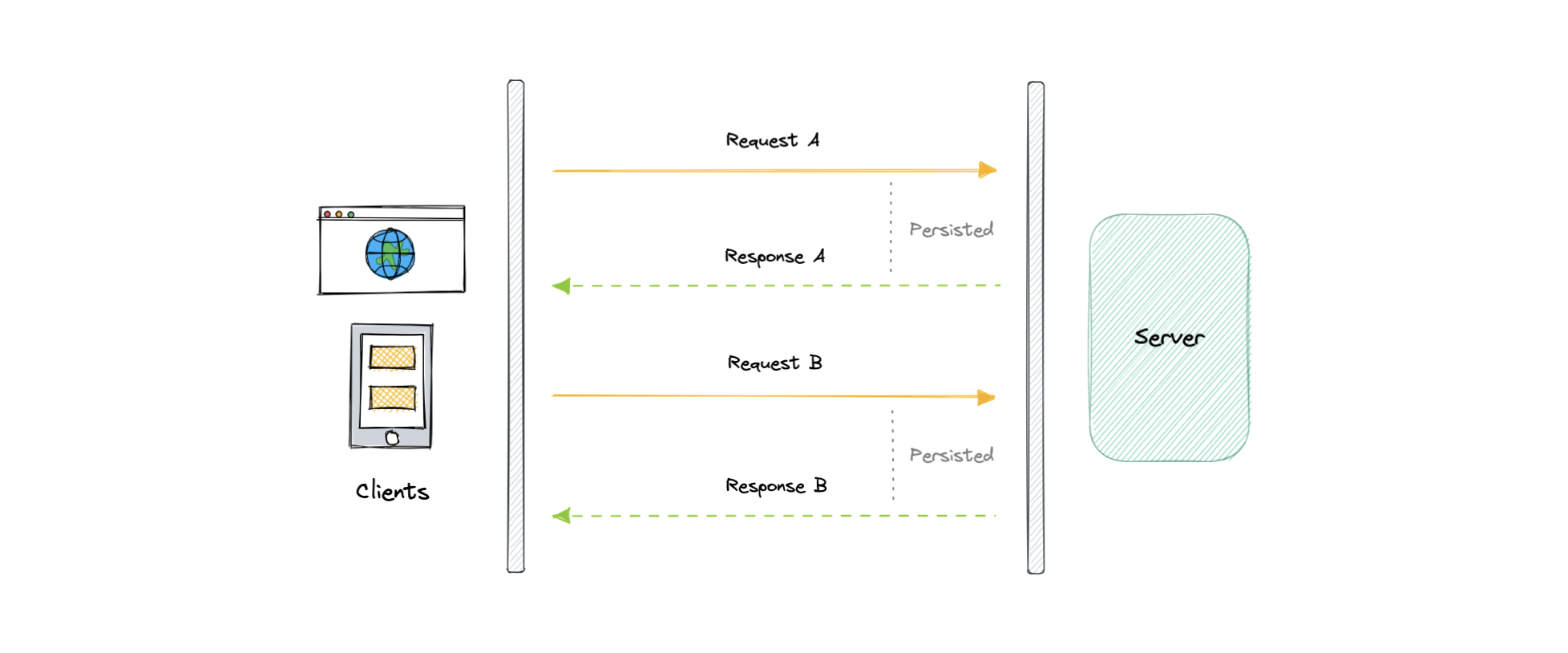
Once the client receives a response, it immediately sends a new request to the server to have a new pending connection to send data to the client, and the operation is repeated. With this approach, the server emulates a real-time server push feature.
Working
Let’s understand how long polling works:
- The client makes an initial request and waits for a response.
- The server receives the request and delays sending anything until an update is available.
- Once an update is available, the response is sent to the client.
- The client receives the response and makes a new request immediately or after some defined interval to establish a connection again.
Advantages
Here are some advantages of long polling:
- Easy to implement, good for small-scale projects.
- Nearly universally supported.
Disadvantages
A major downside of long polling is that it is usually not scalable. Below are some of the other reasons:
- Creates a new connection each time, which can be intensive on the server.
- Reliable message ordering can be an issue for multiple requests.
- Increased latency as the server needs to wait for a new request.
WebSockets
WebSocket provides full-duplex communication channels over a single TCP connection. It is a persistent connection between a client and a server that both parties can use to start sending data at any time.
The client establishes a WebSocket connection through a process known as the WebSocket handshake. If the process succeeds, then the server and client can exchange data in both directions at any time. The WebSocket protocol enables the communication between a client and a server with lower overheads, facilitating real-time data transfer from and to the server.
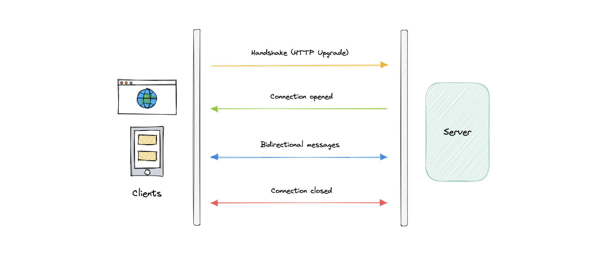
This is made possible by providing a standardized way for the server to send content to the client without being asked and allowing for messages to be passed back and forth while keeping the connection open.
Working
Let’s understand how WebSockets work:
- The client initiates a WebSocket handshake process by sending a request.
- The request also contains an HTTP Upgrade header that allows the request to switch to the WebSocket protocol (
ws://). - The server sends a response to the client, acknowledging the WebSocket handshake request.
- A WebSocket connection will be opened once the client receives a successful handshake response.
- Now the client and server can start sending data in both directions allowing real-time communication.
- The connection is closed once the server or the client decides to close the connection.
Advantages
Below are some advantages of WebSockets:
- Full-duplex asynchronous messaging.
- Better origin-based security model.
- Lightweight for both client and server.
Disadvantages
Let’s discuss some disadvantages of WebSockets:
- Terminated connections aren’t automatically recovered.
- Older browsers don’t support WebSockets (becoming less relevant).
Server-Sent Events (SSE)
Server-Sent Events (SSE) is a way of establishing long-term communication between client and server that enables the server to proactively push data to the client.
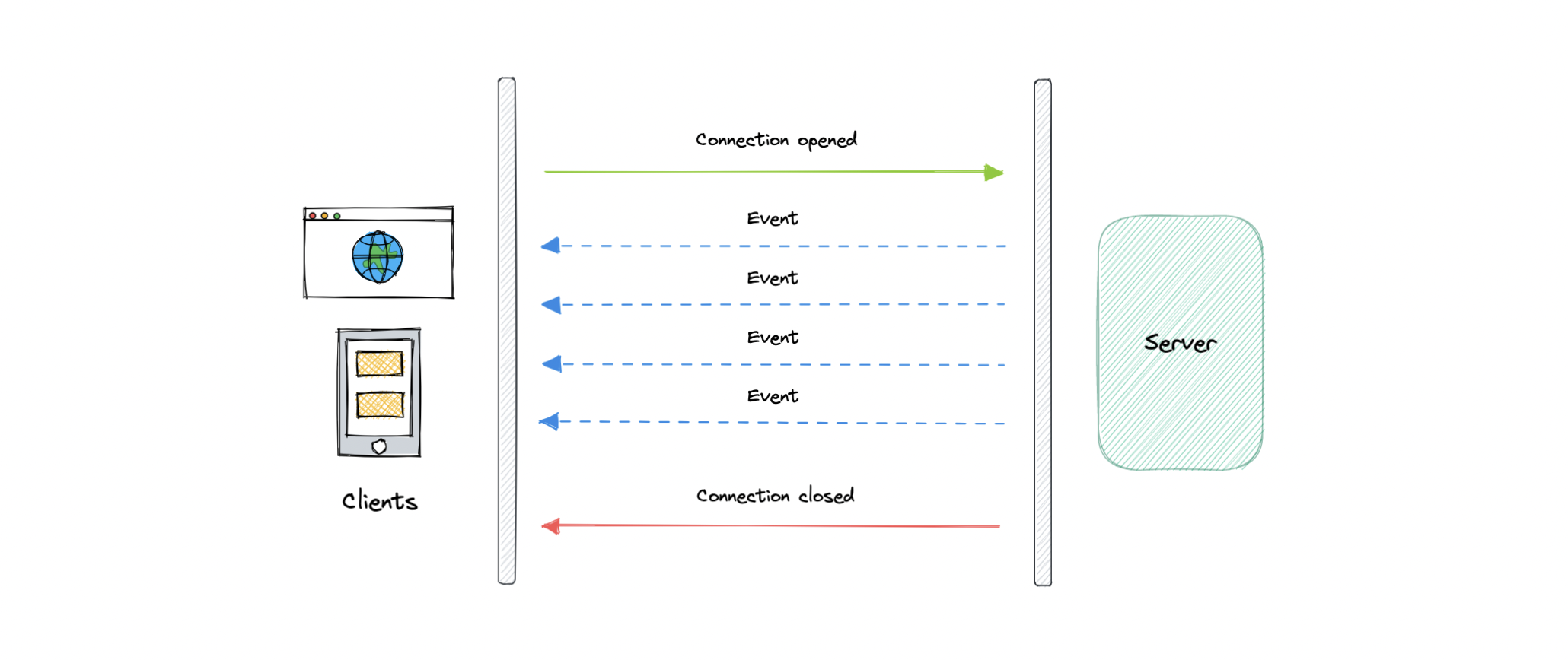
It is unidirectional, meaning once the client sends the request it can only receive the responses without the ability to send new requests over the same connection.
Working
Let’s understand how server-sent events work:
- The client makes a request to the server.
- The connection between client and server is established and it remains open.
- The server sends responses or events to the client when new data is available.
Advantages
- Simple to implement and use for both client and server.
- Supported by most browsers.
- No trouble with firewalls.
Disadvantages
- Unidirectional nature can be limiting.
- Limitation for the maximum number of open connections.
- Does not support binary data.
Geohashing and Quadtrees
Geohashing
Geohashing is a geocoding method used to encode geographic coordinates such as latitude and longitude into short alphanumeric strings. It was created by Gustavo Niemeyer in 2008.
For example, San Francisco with coordinates 37.7564, -122.4016 can be represented in geohash as 9q8yy9mf.
How does Geohashing work?
Geohash is a hierarchical spatial index that uses Base-32 alphabet encoding, the first character in a geohash identifies the initial location as one of the 32 cells. This cell will also contain 32 cells. This means that to represent a point, the world is recursively divided into smaller and smaller cells with each additional bit until the desired precision is attained. The precision factor also determines the size of the cell.

Geohashing guarantees that points are spatially closer if their Geohashes share a longer prefix which means the more characters in the string, the more precise the location. For example, geohashes 9q8yy9mf and 9q8yy9vx are spatially closer as they share the prefix 9q8yy9.
Geohashing can also be used to provide a degree of anonymity as we don’t need to expose the exact location of the user because depending on the length of the geohash we just know they are somewhere within an area.
The cell sizes of the geohashes of different lengths are as follows:
| Geohash length | Cell width | Cell height |
|---|---|---|
| 1 | 5000 km | 5000 km |
| 2 | 1250 km | 1250 km |
| 3 | 156 km | 156 km |
| 4 | 39.1 km | 19.5 km |
| 5 | 4.89 km | 4.89 km |
| 6 | 1.22 km | 0.61 km |
| 7 | 153 m | 153 m |
| 8 | 38.2 m | 19.1 m |
| 9 | 4.77 m | 4.77 m |
| 10 | 1.19 m | 0.596 m |
| 11 | 149 mm | 149 mm |
| 12 | 37.2 mm | 18.6 mm |
Use cases
Here are some common use cases for Geohashing:
- It is a simple way to represent and store a location in a database.
- It can also be shared on social media as URLs since it is easier to share, and remember than latitudes and longitudes.
- We can efficiently find the nearest neighbors of a point through very simple string comparisons and efficient searching of indexes.
Examples
Geohashing is widely used and it is supported by popular databases.
Quadtrees
A quadtree is a tree data structure in which each internal node has exactly four children. They are often used to partition a two-dimensional space by recursively subdividing it into four quadrants or regions. Each child or leaf node stores spatial information. Quadtrees are the two-dimensional analog of Octrees which are used to partition three-dimensional space.
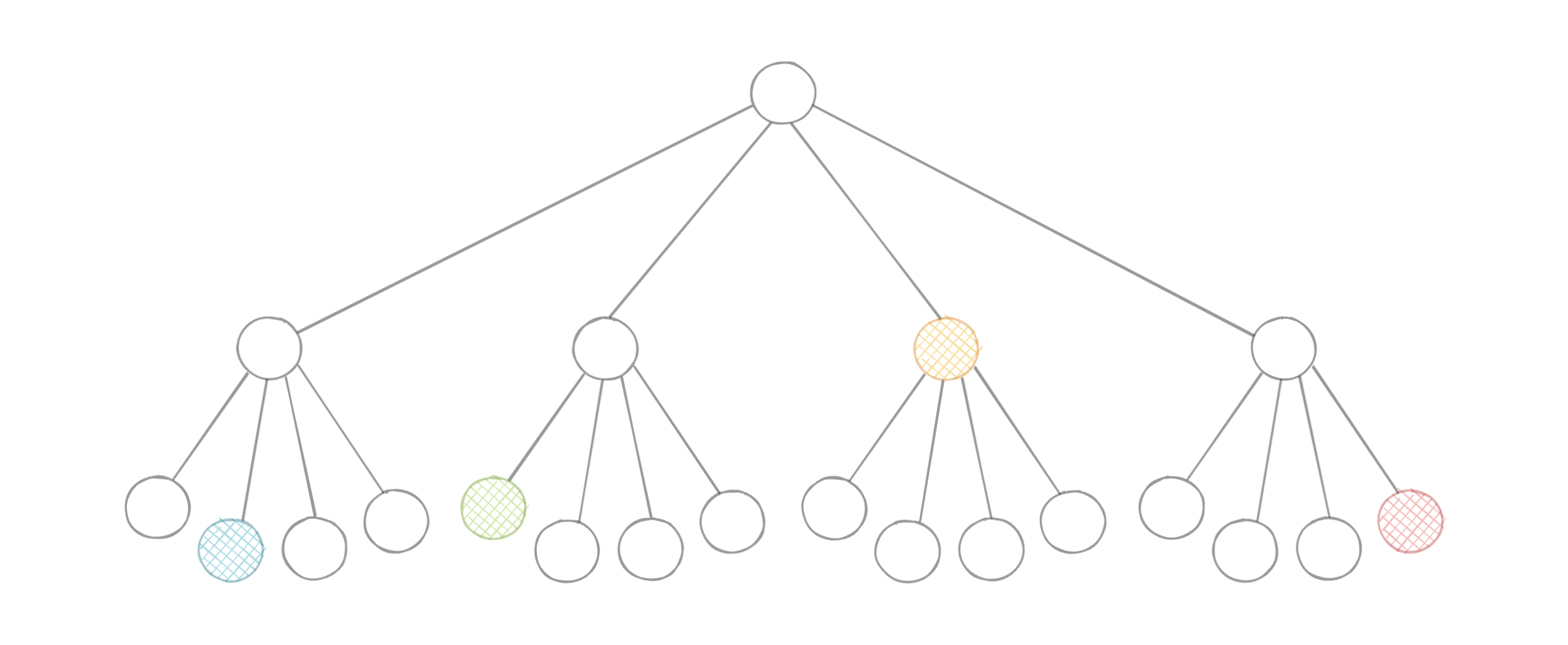
Types of Quadtrees
Quadtrees may be classified according to the type of data they represent, including areas, points, lines, and curves. The following are common types of quadtrees:
- Point quadtrees
- Point-region (PR) quadtrees
- Polygonal map (PM) quadtrees
- Compressed quadtrees
- Edge quadtrees
Why do we need Quadtrees?
Aren’t latitude and longitude enough? Why do we need quadtrees? While in theory using latitude and longitude we can determine things such as how close points are to each other using euclidean distance, for practical use cases it is simply not scalable because of its CPU-intensive nature with large data sets.

Quadtrees enable us to search points within a two-dimensional range efficiently, where those points are defined as latitude/longitude coordinates or as cartesian (x, y) coordinates. Additionally, we can save further computation by only subdividing a node after a certain threshold. And with the application of mapping algorithms such as the Hilbert curve, we can easily improve range query performance.
Use cases
Below are some common uses of quadtrees:
- Image representation, processing, and compression.
- Spacial indexing and range queries.
- Location-based services like Google Maps, Uber, etc.
- Mesh generation and computer graphics.
- Sparse data storage.
Circuit breaker
The circuit breaker is a design pattern used to detect failures and encapsulates the logic of preventing a failure from constantly recurring during maintenance, temporary external system failure, or unexpected system difficulties.
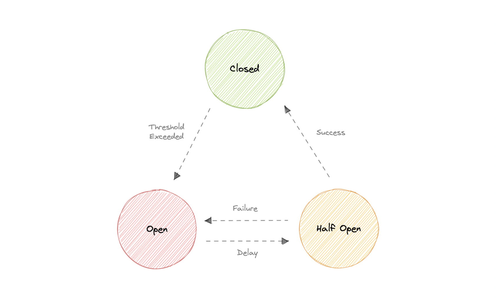
The basic idea behind the circuit breaker is very simple. We wrap a protected function call in a circuit breaker object, which monitors for failures. Once the failures reach a certain threshold, the circuit breaker trips, and all further calls to the circuit breaker return with an error, without the protected call being made at all. Usually, we’ll also want some kind of monitor alert if the circuit breaker trips.
Why do we need circuit breaking?
It’s common for software systems to make remote calls to software running in different processes, probably on different machines across a network. One of the big differences between in-memory calls and remote calls is that remote calls can fail, or hang without a response until some timeout limit is reached. What’s worse if we have many callers on an unresponsive supplier, then we can run out of critical resources leading to cascading failures across multiple systems.
States
Let’s discuss circuit breaker states:
Closed
When everything is normal, the circuit breakers remain closed, and all the request passes through to the services as normal. If the number of failures increases beyond the threshold, the circuit breaker trips and goes into an open state.
Open
In this state circuit breaker returns an error immediately without even invoking the services. The Circuit breakers move into the half-open state after a certain timeout period elapses. Usually, it will have a monitoring system where the timeout will be specified.
Half-open
In this state, the circuit breaker allows a limited number of requests from the service to pass through and invoke the operation. If the requests are successful, then the circuit breaker will go to the closed state. However, if the requests continue to fail, then it goes back to the open state.
Rate Limiting
Rate limiting refers to preventing the frequency of an operation from exceeding a defined limit. In large-scale systems, rate limiting is commonly used to protect underlying services and resources. Rate limiting is generally used as a defensive mechanism in distributed systems, so that shared resources can maintain availability. It also protects our APIs from unintended or malicious overuse by limiting the number of requests that can reach our API in a given period of time.
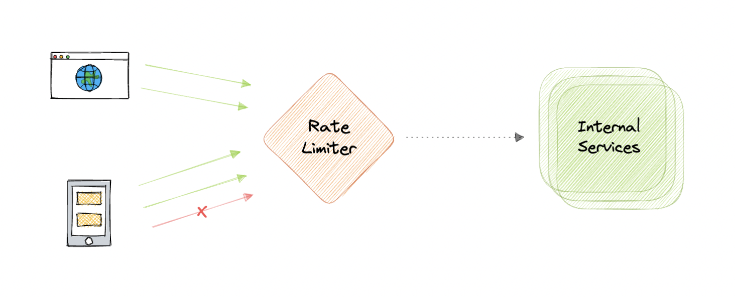
Why do we need Rate Limiting?
Rate limiting is a very important part of any large-scale system and it can be used to accomplish the following:
- Avoid resource starvation as a result of Denial of Service (DoS) attacks.
- Rate Limiting helps in controlling operational costs by putting a virtual cap on the auto-scaling of resources which if not monitored might lead to exponential bills.
- Rate limiting can be used as defense or mitigation against some common attacks.
- For APIs that process massive amounts of data, rate limiting can be used to control the flow of that data.
Algorithms
There are various algorithms for API rate limiting, each with its advantages and disadvantages. Let’s briefly discuss some of these algorithms:
Leaky Bucket
Leaky Bucket is an algorithm that provides a simple, intuitive approach to rate limiting via a queue. When registering a request, the system appends it to the end of the queue. Processing for the first item on the queue occurs at a regular interval or first-in, first-out (FIFO). If the queue is full, then additional requests are discarded (or leaked).
Token Bucket
Here we use a concept of a bucket. When a request comes in, a token from the bucket must be taken and processed. The request will be refused if no token is available in the bucket, and the requester will have to try again later. As a result, the token bucket gets refreshed after a certain time period.
Fixed Window
The system uses a window size of n seconds to track the fixed window algorithm rate. Each incoming request increments the counter for the window. It discards the request if the counter exceeds a threshold.
Sliding Log
Sliding Log rate-limiting involves tracking a time-stamped log for each request. The system stores these logs in a time-sorted hash set or table. It also discards logs with timestamps beyond a threshold. When a new request comes in, we calculate the sum of logs to determine the request rate. If the request would exceed the threshold rate, then it is held.
Sliding Window
Sliding Window is a hybrid approach that combines the fixed window algorithm’s low processing cost and the sliding log’s improved boundary conditions. Like the fixed window algorithm, we track a counter for each fixed window. Next, we account for a weighted value of the previous window’s request rate based on the current timestamp to smooth out bursts of traffic.
Rate Limiting in Distributed Systems
Rate Limiting becomes complicated when distributed systems are involved. The two broad problems that come with rate limiting in distributed systems are:
Inconsistencies
When using a cluster of multiple nodes, we might need to enforce a global rate limit policy. Because if each node were to track its rate limit, a consumer could exceed a global rate limit when sending requests to different nodes. The greater the number of nodes, the more likely the user will exceed the global limit.
The simplest way to solve this problem is to use sticky sessions in our load balancers so that each consumer gets sent to exactly one node but this causes a lack of fault tolerance and scaling problems. Another approach might be to use a centralized data store like Redis but this will increase latency and cause race conditions.
Race Conditions
This issue happens when we use a naive “get-then-set” approach, in which we retrieve the current rate limit counter, increment it, and then push it back to the datastore. This model’s problem is that additional requests can come through in the time it takes to perform a full cycle of read-increment-store, each attempting to store the increment counter with an invalid (lower) counter value. This allows a consumer to send a very large number of requests to bypass the rate limiting controls.
One way to avoid this problem is to use some sort of distributed locking mechanism around the key, preventing any other processes from accessing or writing to the counter. Though the lock will become a significant bottleneck and will not scale well. A better approach might be to use a “set-then-get” approach, allowing us to quickly increment and check counter values without letting the atomic operations get in the way.
Service Discovery
Service discovery is the detection of services within a computer network. Service Discovery Protocol (SDP) is a networking standard that accomplishes the detection of networks by identifying resources.
Why do we need Service Discovery?
In a monolithic application, services invoke one another through language-level methods or procedure calls. However, modern microservices-based applications typically run in virtualized or containerized environments where the number of instances of a service and their locations change dynamically. Consequently, we need a mechanism that enables the clients of service to make requests to a dynamically changing set of ephemeral service instances.
Implementations
There are two main service discovery patterns:
Client-side discovery
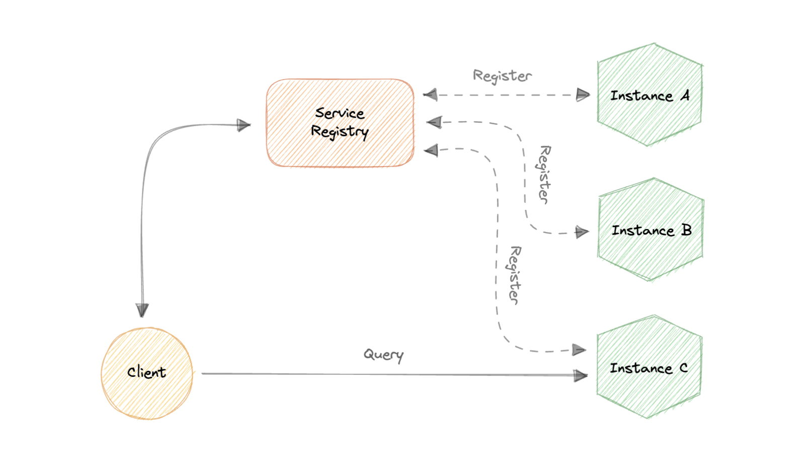
In this approach, the client obtains the location of another service by querying a service registry which is responsible for managing and storing the network locations of all the services.
Server-side discovery
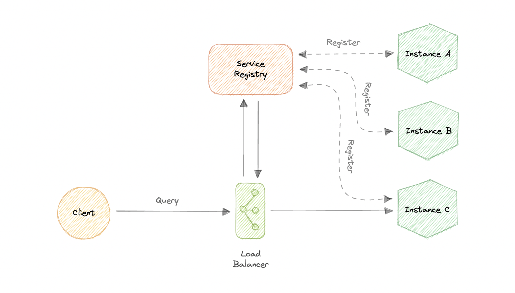
In this approach, we use an intermediate component such as a load balancer. The client makes a request to the service via a load balancer which then forwards the request to an available service instance.
Service Registry
A service registry is basically a database containing the network locations of service instances to which the clients can reach out. A Service Registry must be highly available and up-to-date.
Service Registration
We also need a way to obtain service information, often known as service registration. Let’s look at two possible service registration approaches:
Self-Registration
When using the self-registration model, a service instance is responsible for registering and de-registering itself in the Service Registry. In addition, if necessary, a service instance sends heartbeat requests to keep its registration alive.
Third-party Registration
The registry keeps track of changes to running instances by polling the deployment environment or subscribing to events. When it detects a newly available service instance, it records it in its database. The Service Registry also de-registers terminated service instances.
Service mesh
Service-to-service communication is essential in a distributed application but routing this communication, both within and across application clusters, becomes increasingly complex as the number of services grows. Service mesh enables managed, observable, and secure communication between individual services. It works with a service discovery protocol to detect services. Istio and envoy are some of the most commonly used service mesh technologies.
Examples
Here are some commonly used service discovery infrastructure tools:
SLA, SLO, SLI
Let’s briefly discuss SLA, SLO, and SLI. These are mostly related to the business and site reliability side of things but good to know nonetheless.
Why are they important?
SLAs, SLOs, and SLIs allow companies to define, track and monitor the promises made for a service to its users. Together, SLAs, SLOs, and SLIs should help teams generate more user trust in their services with an added emphasis on continuous improvement to incident management and response processes.
SLA
An SLA, or Service Level Agreement, is an agreement made between a company and its users of a given service. The SLA defines the different promises that the company makes to users regarding specific metrics, such as service availability.
SLAs are often written by a company’s business or legal team.
SLO
An SLO, or Service Level Objective, is the promise that a company makes to users regarding a specific metric such as incident response or uptime. SLOs exist within an SLA as individual promises contained within the full user agreement. The SLO is the specific goal that the service must meet in order to comply with the SLA. SLOs should always be simple, clearly defined, and easily measured to determine whether or not the objective is being fulfilled.
SLI
An SLI, or Service Level Indicator, is a key metric used to determine whether or not the SLO is being met. It is the measured value of the metric described within the SLO. In order to remain in compliance with the SLA, the SLI’s value must always meet or exceed the value determined by the SLO.
Disaster recovery
Disaster recovery (DR) is a process of regaining access and functionality of the infrastructure after events like a natural disaster, cyber attack, or even business disruptions.
Disaster recovery relies upon the replication of data and computer processing in an off-premises location not affected by the disaster. When servers go down because of a disaster, a business needs to recover lost data from a second location where the data is backed up. Ideally, an organization can transfer its computer processing to that remote location as well in order to continue operations.
Disaster Recovery is often not actively discussed during system design interviews but it’s important to have some basic understanding of this topic. You can learn more about disaster recovery from AWS Well-Architected Framework.
Why is disaster recovery important?
Disaster recovery can have the following benefits:
- Minimize interruption and downtime
- Limit damages
- Fast restoration
- Better customer retention
Terms
Let’s discuss some important terms relevantly for disaster recovery:

RTO
Recovery Time Objective (RTO) is the maximum acceptable delay between the interruption of service and restoration of service. This determines what is considered an acceptable time window when service is unavailable.
RPO
Recovery Point Objective (RPO) is the maximum acceptable amount of time since the last data recovery point. This determines what is considered an acceptable loss of data between the last recovery point and the interruption of service.
Strategies
A variety of disaster recovery (DR) strategies can be part of a disaster recovery plan.
Back-up
This is the simplest type of disaster recovery and involves storing data off-site or on a removable drive.
Cold Site
In this type of disaster recovery, an organization sets up basic infrastructure in a second site.
Hot site
A hot site maintains up-to-date copies of data at all times. Hot sites are time-consuming to set up and more expensive than cold sites, but they dramatically reduce downtime.
Virtual Machines (VMs) and Containers
Before we discuss virtualization vs containerization, let’s learn what are virtual machines (VMs) and Containers.
Virtual Machines (VM)
A Virtual Machine (VM) is a virtual environment that functions as a virtual computer system with its own CPU, memory, network interface, and storage, created on a physical hardware system. A software called a hypervisor separates the machine’s resources from the hardware and provisions them appropriately so they can be used by the VM.
VMs are isolated from the rest of the system, and multiple VMs can exist on a single piece of hardware, like a server. They can be moved between host servers depending on the demand or to use resources more efficiently.
What is a Hypervisor?
A Hypervisor sometimes called a Virtual Machine Monitor (VMM), isolates the operating system and resources from the virtual machines and enables the creation and management of those VMs. The hypervisor treats resources like CPU, memory, and storage as a pool of resources that can be easily reallocated between existing guests or new virtual machines.
Why use a Virtual Machine?
Server consolidation is a top reason to use VMs. Most operating system and application deployments only use a small amount of the physical resources available. By virtualizing our servers, we can place many virtual servers onto each physical server to improve hardware utilization. This keeps us from needing to purchase additional physical resources.
A VM provides an environment that is isolated from the rest of a system, so whatever is running inside a VM won’t interfere with anything else running on the host hardware. Because VMs are isolated, they are a good option for testing new applications or setting up a production environment. We can also run a single-purpose VM to support a specific use case.
Containers
A container is a standard unit of software that packages up code and all its dependencies such as specific versions of runtimes and libraries so that the application runs quickly and reliably from one computing environment to another. Containers offer a logical packaging mechanism in which applications can be abstracted from the environment in which they actually run. This decoupling allows container-based applications to be deployed easily and consistently, regardless of the target environment.
Why do we need containers?
Let’s discuss some advantages of using containers:
Separation of responsibility
Containerization provides a clear separation of responsibility, as developers focus on application logic and dependencies, while operations teams can focus on deployment and management.
Workload portability
Containers can run virtually anywhere, greatly easing development and deployment.
Application isolation
Containers virtualize CPU, memory, storage, and network resources at the operating system level, providing developers with a view of the OS logically isolated from other applications.
Agile development
Containers allow developers to move much more quickly by avoiding concerns about dependencies and environments.
Efficient operations
Containers are lightweight and allow us to use just the computing resources we need.
Virtualization vs Containerization
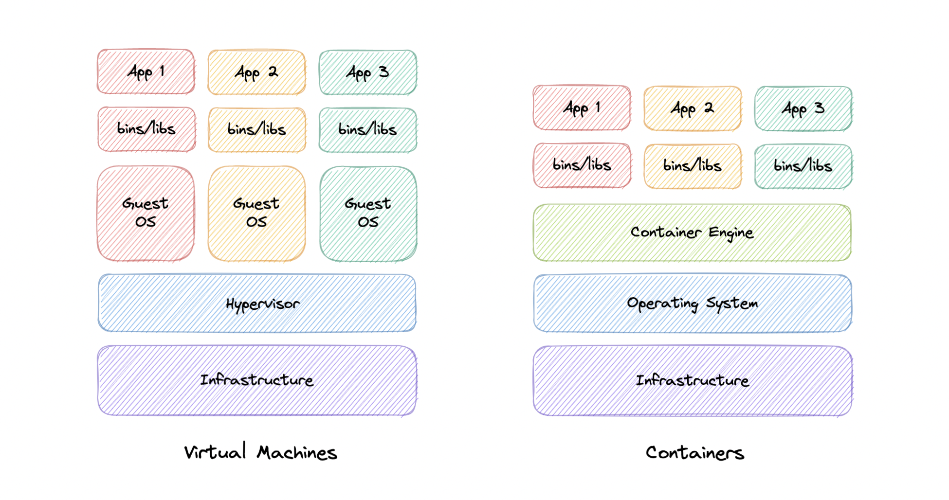
In traditional virtualization, a hypervisor virtualizes physical hardware. The result is that each virtual machine contains a guest OS, a virtual copy of the hardware that the OS requires to run, and an application and its associated libraries and dependencies.
Instead of virtualizing the underlying hardware, containers virtualize the operating system so each container contains only the application and its dependencies making them much more lightweight than VMs. Containers also share the OS kernel and use a fraction of the memory VMs require.
OAuth 2.0 and OpenID Connect (OIDC)
OAuth 2.0
OAuth 2.0, which stands for Open Authorization, is a standard designed to provide consented access to resources on behalf of the user, without ever sharing the user’s credentials. OAuth 2.0 is an authorization protocol and not an authentication protocol, it is designed primarily as a means of granting access to a set of resources, for example, remote APIs or user’s data.
Concepts
The OAuth 2.0 protocol defines the following entities:
- Resource Owner: The user or system that owns the protected resources and can grant access to them.
- Client: The client is the system that requires access to the protected resources.
- Authorization Server: This server receives requests from the Client for Access Tokens and issues them upon successful authentication and consent by the Resource Owner.
- Resource Server: A server that protects the user’s resources and receives access requests from the Client. It accepts and validates an Access Token from the Client and returns the appropriate resources.
- Scopes: They are used to specify exactly the reason for which access to resources may be granted. Acceptable scope values, and which resources they relate to, are dependent on the Resource Server.
- Access Token: A piece of data that represents the authorization to access resources on behalf of the end-user.
How does OAuth 2.0 work?
Let’s learn how OAuth 2.0 works:
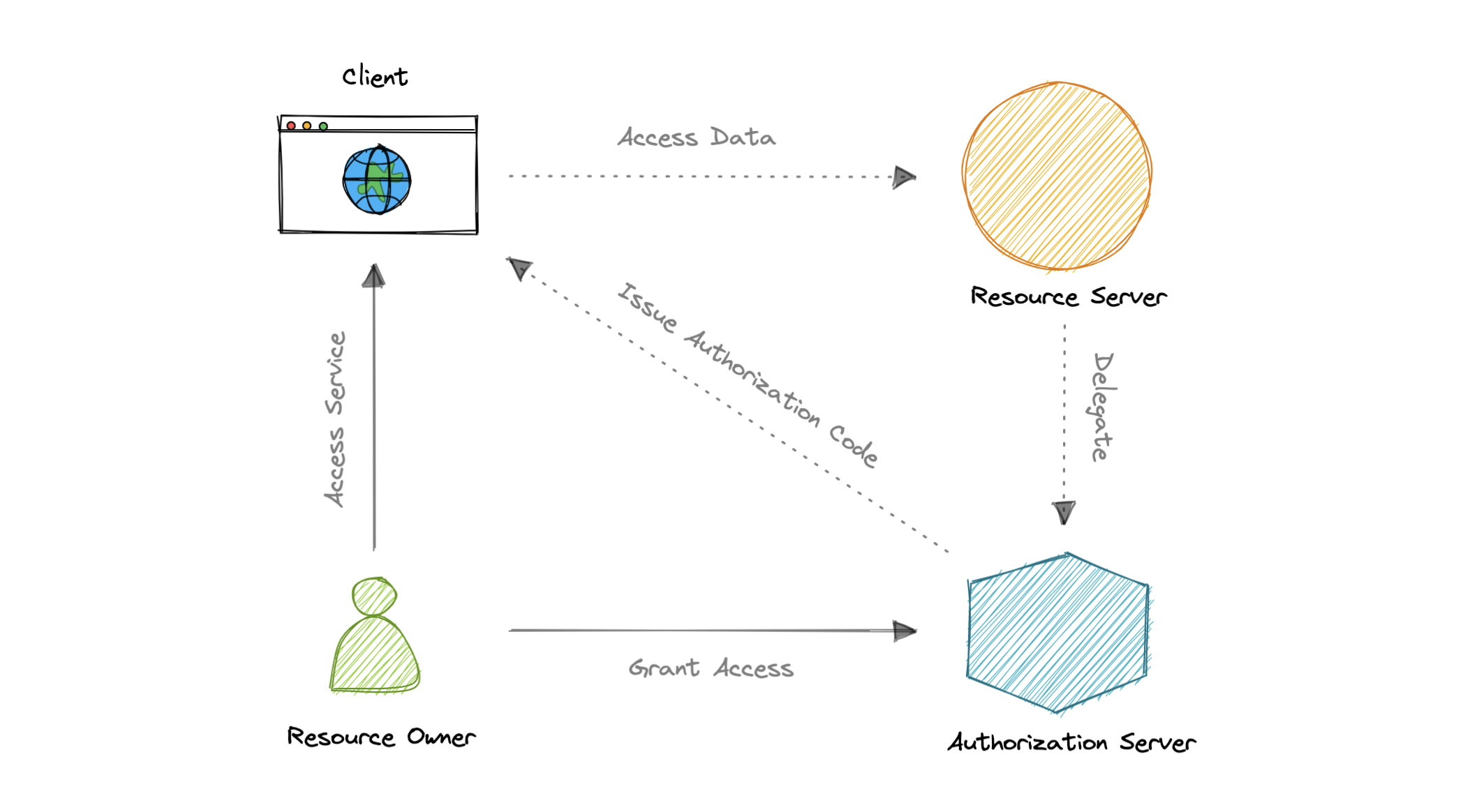
- The client requests authorization from the Authorization Server, supplying the client id and secret as identification. It also provides the scopes and an endpoint URI to send the Access Token or the Authorization Code.
- The Authorization Server authenticates the client and verifies that the requested scopes are permitted.
- The resource owner interacts with the authorization server to grant access.
- The Authorization Server redirects back to the client with either an Authorization Code or Access Token, depending on the grant type. A Refresh Token may also be returned.
- With the Access Token, the client can request access to the resource from the Resource Server.
Disadvantages
Here are the most common disadvantages of OAuth 2.0:
- Lacks built-in security features.
- No standard implementation.
- No common set of scopes.
OpenID Connect
OAuth 2.0 is designed only for authorization, for granting access to data and features from one application to another. OpenID Connect (OIDC) is a thin layer that sits on top of OAuth 2.0 that adds login and profile information about the person who is logged in.
When an Authorization Server supports OIDC, it is sometimes called an identity provider (IdP), since it provides information about the Resource Owner back to the Client. OpenID Connect is relatively new, resulting in lower adoption and industry implementation of best practices compared to OAuth.
Concepts
The OpenID Connect (OIDC) protocol defines the following entities:
- Relying Party: The current application.
- OpenID Provider: This is essentially an intermediate service that provides a one-time code to the Relying Party.
- Token Endpoint: A web server that accepts the One-Time Code (OTC) and provides an access code that’s valid for an hour. The main difference between OIDC and OAuth 2.0 is that the token is provided using JSON Web Token (JWT).
- UserInfo Endpoint: The Relying Party communicates with this endpoint, providing a secure token and receiving information about the end-user
Both OAuth 2.0 and OIDC are easy to implement and are JSON based, which is supported by most web and mobile applications. However, the OpenID Connect (OIDC) specification is more strict than that of basic OAuth.
Single Sign-On (SSO)
Single Sign-On (SSO) is an authentication process in which a user is provided access to multiple applications or websites by using only a single set of login credentials. This prevents the need for the user to log separately into the different applications.
The user credentials and other identifying information are stored and managed by a centralized system called Identity Provider (IdP). The Identity Provider is a trusted system that provides access to other websites and applications.
Single Sign-On (SSO) based authentication systems are commonly used in enterprise environments where employees require access to multiple applications of their organizations.
Components
Let’s discuss some key components of Single Sign-On (SSO).
Identity Provider (IdP)
User Identity information is stored and managed by a centralized system called Identity Provider (IdP). The Identity Provider authenticates the user and provides access to the service provider.
The identity provider can directly authenticate the user by validating a username and password or by validating an assertion about the user’s identity as presented by a separate identity provider. The identity provider handles the management of user identities in order to free the service provider from this responsibility.
Service Provider
A service provider provides services to the end-user. They rely on identity providers to assert the identity of a user, and typically certain attributes about the user are managed by the identity provider. Service providers may also maintain a local account for the user along with attributes that are unique to their service.
Identity Broker
An identity broker acts as an intermediary that connects multiple service providers with various different identity providers. Using Identity Broker, we can perform single sign-on over any application without the hassle of the protocol it follows.
SAML
Security Assertion Markup Language is an open standard that allows clients to share security information about identity, authentication, and permission across different systems. SAML is implemented with the Extensible Markup Language (XML) standard for sharing data.
SAML specifically enables identity federation, making it possible for identity providers (IdPs) to seamlessly and securely pass authenticated identities and their attributes to service providers.
How does SSO work?
Now, let’s discuss how Single Sign-On works:
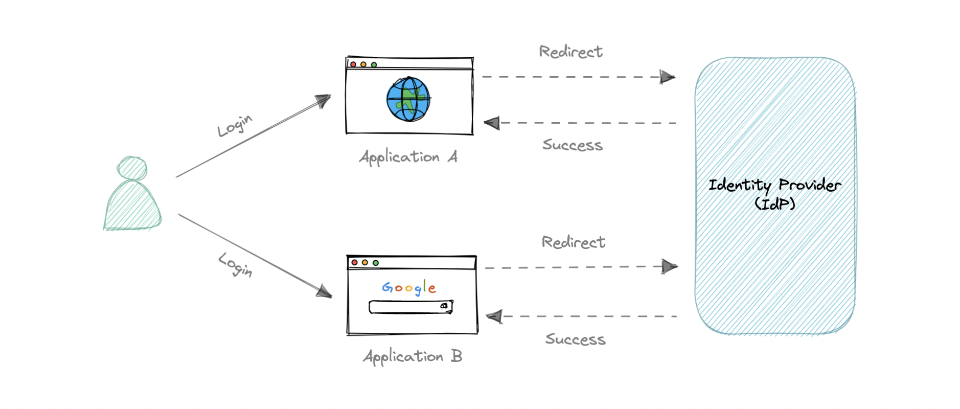
- The user requests a resource from their desired application.
- The application redirects the user to the Identity Provider (IdP) for authentication.
- The user signs in with their credentials (usually, username and password).
- Identity Provider (IdP) sends a Single Sign-On response back to the client application.
- The application grants access to the user.
SAML vs OAuth 2.0 and OpenID Connect (OIDC)
There are many differences between SAML, OAuth, and OIDC. SAML uses XML to pass messages, while OAuth and OIDC use JSON. OAuth provides a simpler experience, while SAML is geared towards enterprise security.
OAuth and OIDC use RESTful communication extensively, which is why mobile, and modern web applications find OAuth and OIDC a better experience for the user. SAML, on the other hand, drops a session cookie in a browser that allows a user to access certain web pages. This is great for short-lived workloads.
OIDC is developer-friendly and simpler to implement, which broadens the use cases for which it might be implemented. It can be implemented from scratch pretty fast, via freely available libraries in all common programming languages. SAML can be complex to install and maintain, which only enterprise-size companies can handle well.
OpenID Connect is essentially a layer on top of the OAuth framework. Therefore, it can offer a built-in layer of permission that asks a user to agree to what the service provider might access. Although SAML is also capable of allowing consent flow, it achieves this by hard-coding carried out by a developer and not as part of its protocol.
Both of these authentication protocols are good at what they do. As always, a lot depends on our specific use cases and target audience.
Advantages
Following are the benefits of using Single Sign-On:
- Ease of use as users only need to remember one set of credentials.
- Ease of access without having to go through a lengthy authorization process.
- Enforced security and compliance to protect sensitive data.
- Simplifying the management with reduced IT support cost and admin time.
Disadvantages
Here are some disadvantages of Single Sign-On:
- Single Password Vulnerability, if the main SSO password gets compromised, all the supported applications get compromised.
- The authentication process using Single Sign-On is slower than traditional authentication as every application has to request the SSO provider for verification.
Examples
These are some commonly used Identity Providers (IdP):
SSL, TLS, mTLS
Let’s briefly discuss some important communication security protocols such as SSL, TLS, and mTLS. I would say that from a “big picture” system design perspective, this topic is not very important but still good to know about.
SSL
SSL stands for Secure Sockets Layer, and it refers to a protocol for encrypting and securing communications that take place on the internet. It was first developed in 1995 but since has been deprecated in favor of TLS (Transport Layer Security).
Why is it called an SSL certificate if it is deprecated?
Most major certificate providers still refer to certificates as SSL certificates, which is why the naming convention persists.
Why was SSL so important?
Originally, data on the web was transmitted in plaintext that anyone could read if they intercepted the message. SSL was created to correct this problem and protect user privacy. By encrypting any data that goes between the user and a web server, SSL also stops certain kinds of cyber attacks by preventing attackers from tampering with data in transit.
TLS
Transport Layer Security, or TLS, is a widely adopted security protocol designed to facilitate privacy and data security for communications over the internet. TLS evolved from a previous encryption protocol called Secure Sockets Layer (SSL). A primary use case of TLS is encrypting the communication between web applications and servers.
There are three main components to what the TLS protocol accomplishes:
- Encryption: hides the data being transferred from third parties.
- Authentication: ensures that the parties exchanging information are who they claim to be.
- Integrity: verifies that the data has not been forged or tampered with.
mTLS
Mutual TLS, or mTLS, is a method for mutual authentication. mTLS ensures that the parties at each end of a network connection are who they claim to be by verifying that they both have the correct private key. The information within their respective TLS certificates provides additional verification.
Why use mTLS?
mTLS helps ensure that the traffic is secure and trusted in both directions between a client and server. This provides an additional layer of security for users who log in to an organization’s network or applications. It also verifies connections with client devices that do not follow a login process, such as Internet of Things (IoT) devices.
Nowadays, mTLS is commonly used by microservices or distributed systems in a zero trust security model to verify each other.
System Design Interviews
System design is a very extensive topic and system design interviews are designed to evaluate your capability to produce technical solutions to abstract problems, as such, they’re not designed for a specific answer. The unique aspect of system design interviews is the two-way nature between the candidate and the interviewer.
Expectations are quite different at different engineering levels as well. Because someone with a lot of practical experience will approach it quite differently from someone who’s new in the industry. As a result, it’s hard to come up with a single strategy that will help us stay organized during the interview.
Let’s look at some common strategies for system design interviews:
Requirements clarifications
System design interview questions, by nature, are vague or abstract. Asking questions about the exact scope of the problem, and clarifying functional requirements early in the interview is essential. Usually, requirements are divided into three parts:
Functional requirements
These are the requirements that the end user specifically demands as basic functionalities that the system should offer. All these functionalities need to be necessarily incorporated into the system as part of the contract.
For example:
- “What are the features that we need to design for this system?”
- “What are the edge cases we need to consider, if any, in our design?”
Non-functional requirements
These are the quality constraints that the system must satisfy according to the project contract. The priority or extent to which these factors are implemented varies from one project to another. They are also called non-behavioral requirements. For example, portability, maintainability, reliability, scalability, security, etc.
For example:
- “Each request should be processed with the minimum latency”
- “System should be highly available”
Extended requirements
These are basically “nice to have” requirements that might be out of the scope of the system.
For example:
- “Our system should record metrics and analytics”
- “Service health and performance monitoring?”
Estimation and Constraints
Estimate the scale of the system we’re going to design. It is important to ask questions such as:
- “What is the desired scale that this system will need to handle?”
- “What is the read/write ratio of our system?”
- “How many requests per second?”
- “How much storage will be needed?”
These questions will help us scale our design later.
Data model design
Once we have the estimations, we can start with defining the database schema. Doing so in the early stages of the interview would help us to understand the data flow which is the core of every system. In this step, we basically define all the entities and relationships between them.
- “What are the different entities in the system?”
- “What are the relationships between these entities?”
- “How many tables do we need?”
- “Is NoSQL a better choice here?”
API design
Next, we can start designing APIs for the system. These APIs will help us define the expectations from the system explicitly. We don’t have to write any code, just a simple interface defining the API requirements such as parameters, functions, classes, types, entities, etc.
For example:
createUser(name: string, email: string): User
It is advised to keep the interface as simple as possible and come back to it later when covering extended requirements.
High-level component design
Now we have established our data model and API design, it’s time to identify system components (such as Load Balancers, API Gateway, etc.) that are needed to solve our problem and draft the first design of our system.
- “Is it best to design a monolithic or a microservices architecture?”
- “What type of database should we use?”
Once we have a basic diagram, we can start discussing with the interviewer how the system will work from the client’s perspective.
Detailed design
Now it’s time to go into detail about the major components of the system we designed. As always discuss with the interviewer which component may need further improvements.
Here is a good opportunity to demonstrate your experience in the areas of your expertise. Present different approaches, advantages, and disadvantages. Explain your design decisions, and back them up with examples. This is also a good time to discuss any additional features the system might be able to support, though this is optional.
- “How should we partition our data?”
- “What about load distribution?”
- “Should we use cache?”
- “How will we handle a sudden spike in traffic?”
Also, try not to be too opinionated about certain technologies, statements like “I believe that NoSQL databases are just better, SQL databases are not scalable” reflect poorly. As someone who has interviewed a lot of people over the years, my two cents here would be to be humble about what you know and what you do not. Use your existing knowledge with examples to navigate this part of the interview.
Identify and resolve bottlenecks
Finally, it’s time to discuss bottlenecks and approaches to mitigate them. Here are some important questions to ask:
- “Do we have enough database replicas?”
- “Is there any single point of failure?”
- “Is database sharding required?”
- “How can we make our system more robust?”
- “How to improve the availability of our cache?”
Make sure to read the engineering blog of the company you’re interviewing with. This will help you get a sense of what technology stack they’re using and which problems are important to them.
URL Shortener
Let’s design a URL shortener, similar to services like Bitly, TinyURL.
What is a URL Shortener?
A URL shortener service creates an alias or a short URL for a long URL. Users are redirected to the original URL when they visit these short links.
For example, the following long URL can be changed to a shorter URL.
Long URL: https://karanpratapsingh.com/courses/system-design/url-shortener
Short URL: https://bit.ly/3I71d3o
Why do we need a URL shortener?
URL shortener saves space in general when we are sharing URLs. Users are also less likely to mistype shorter URLs. Moreover, we can also optimize links across devices, this allows us to track individual links.
Requirements
Our URL shortening system should meet the following requirements:
Functional requirements
- Given a URL, our service should generate a shorter and unique alias for it.
- Users should be redirected to the original URL when they visit the short link.
- Links should expire after a default timespan.
Non-functional requirements
- High availability with minimal latency.
- The system should be scalable and efficient.
Extended requirements
- Prevent abuse of services.
- Record analytics and metrics for redirections.
Estimation and Constraints
Let’s start with the estimation and constraints.
Note: Make sure to check any scale or traffic related assumptions with your interviewer.
Traffic
This will be a read-heavy system, so let’s assume a 100:1 read/write ratio with 100 million links generated per month.
Reads/Writes Per month
For reads per month:
\[100 \times 100 \space million = 10 \space billion/month\]Similarly for writes:
\[1 \times 100 \space million = 100 \space million/month\]What would be Requests Per Second (RPS) for our system?
100 million requests per month translate into 40 requests per second.
\[\frac{100 \space million}{(30 \space days \times 24 \space hrs \times 3600 \space seconds)} = \sim 40 \space URLs/second\]And with a 100:1 read/write ratio, the number of redirections will be:
Bandwidth
Since we expect about 40 URLs every second, and if we assume each request is of size 500 bytes then the total incoming data for then write requests would be:
\[40 \times 500 \space bytes = 20 \space KB/second\]Similarly, for the read requests, since we expect about 4K redirections, the total outgoing data would be:
\[4000 \space URLs/second \times 500 \space bytes = \sim 2 \space MB/second\]Storage
For storage, we will assume we store each link or record in our database for 10 years. Since we expect around 100M new requests every month, the total number of records we will need to store would be:
\[100 \space million \times 10\space years \times 12 \space months = 12 \space billion\]Like earlier, if we assume each stored recorded will be approximately 500 bytes. We will need around 6TB of storage:
\[12 \space billion \times 500 \space bytes = 6 \space TB\]Cache
For caching, we will follow the classic Pareto principle also known as the 80/20 rule. This means that 80% of the requests are for 20% of the data, so we can cache around 20% of our requests.
Since we get around 4K read or redirection requests each second. This translates into 350M requests per day.
\[4000 \space URLs/second \times 24 \space hours \times 3600 \space seconds = \sim 350 \space million \space requests/day\]Hence, we will need around 35GB of memory per day.
\[20 \space percent \times 350 \space million \times 500 \space bytes = 35 \space GB/day\]High-level estimate
Here is our high-level estimate:
| Type | Estimate |
|---|---|
| Writes (New URLs) | 40/s |
| Reads (Redirection) | 4K/s |
| Bandwidth (Incoming) | 20 KB/s |
| Bandwidth (Outgoing) | 2 MB/s |
| Storage (10 years) | 6 TB |
| Memory (Caching) | ~35 GB/day |
Data model design
Next, we will focus on the data model design. Here is our database schema:
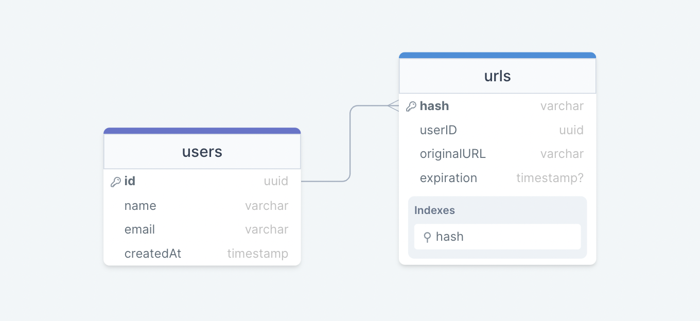
Initially, we can get started with just two tables:
users
Stores user’s details such as name, email, createdAt, etc.
urls
Contains the new short URL’s properties such as expiration, hash, originalURL, and userID of the user who created the short URL. We can also use the hash column as an index to improve the query performance.
What kind of database should we use?
Since the data is not strongly relational, NoSQL databases such as Amazon DynamoDB, Apache Cassandra, or MongoDB will be a better choice here, if we do decide to use an SQL database then we can use something like Azure SQL Database or Amazon RDS.
For more details, refer to SQL vs NoSQL.
API design
Let us do a basic API design for our services:
Create URL
This API should create a new short URL in our system given an original URL.
createURL(apiKey: string, originalURL: string, expiration?: Date): string
Parameters
API Key (string): API key provided by the user.
Original Url (string): Original URL to be shortened.
Expiration (Date): Expiration date of the new URL (optional).
Returns
Short URL (string): New shortened URL.
Get URL
This API should retrieve the original URL from a given short URL.
getURL(apiKey: string, shortURL: string): string
Parameters
API Key (string): API key provided by the user.
Short Url (string): Short URL mapped to the original URL.
Returns
Original URL (string): Original URL to be retrieved.
Delete URL
This API should delete a given shortURL from our system.
deleteURL(apiKey: string, shortURL: string): boolean
Parameters
API Key (string): API key provided by the user.
Short Url (string): Short URL to be deleted.
Returns
Result (boolean): Represents whether the operation was successful or not.
Why do we need an API key?
As you must’ve noticed, we’re using an API key to prevent abuse of our services. Using this API key we can limit the users to a certain number of requests per second or minute. This is quite a standard practice for developer APIs and should cover our extended requirement.
High-level design
Now let us do a high-level design of our system.
URL Encoding
Our system’s primary goal is to shorten a given URL, let’s look at different approaches:
Base62 Approach
In this approach, we can encode the original URL using Base62 which consists of the capital letters A-Z, the lower case letters a-z, and the numbers 0-9.
\[Number \space of \space URLs = 62^N\]Where,
N: Number of characters in the generated URL.
So, if we want to generate a URL that is 7 characters long, we will generate ~3.5 trillion different URLs.
\[\begin{gather*} 62^5 = \sim 916 \space million \space URLs \\ 62^6 = \sim 56.8 \space billion \space URLs \\ 62^7 = \sim 3.5 \space trillion \space URLs \end{gather*}\]This is the simplest solution here, but it does not guarantee non-duplicate or collision-resistant keys.
MD5 Approach
The MD5 message-digest algorithm is a widely used hash function producing a 128-bit hash value (or 32 hexadecimal digits). We can use these 32 hexadecimal digits for generating 7 characters long URL.
\[MD5(original\_url) \rightarrow base62encode \rightarrow hash\]However, this creates a new issue for us, which is duplication and collision. We can try to re-compute the hash until we find a unique one but that will increase the overhead of our systems. It’s better to look for more scalable approaches.
Counter Approach
In this approach, we will start with a single server which will maintain the count of the keys generated. Once our service receives a request, it can reach out to the counter which returns a unique number and increments the counter. When the next request comes the counter again returns the unique number and this goes on.
\[Counter(0-3.5 \space trillion) \rightarrow base62encode \rightarrow hash\]The problem with this approach is that it can quickly become a single point for failure. And if we run multiple instances of the counter we can have collision as it’s essentially a distributed system.
To solve this issue we can use a distributed system manager such as Zookeeper which can provide distributed synchronization. Zookeeper can maintain multiple ranges for our servers.
\[\begin{align*} & Range \space 1: \space 1 \rightarrow 1,000,000 \\ & Range \space 2: \space 1,000,001 \rightarrow 2,000,000 \\ & Range \space 3: \space 2,000,001 \rightarrow 3,000,000 \\ & ... \end{align*}\]Once a server reaches its maximum range Zookeeper will assign an unused counter range to the new server. This approach can guarantee non-duplicate and collision-resistant URLs. Also, we can run multiple instances of Zookeeper to remove the single point of failure.
Key Generation Service (KGS)
As we discussed, generating a unique key at scale without duplication and collisions can be a bit of a challenge. To solve this problem, we can create a standalone Key Generation Service (KGS) that generates a unique key ahead of time and stores it in a separate database for later use. This approach can make things simple for us.
How to handle concurrent access?
Once the key is used, we can mark it in the database to make sure we don’t reuse it, however, if there are multiple server instances reading data concurrently, two or more servers might try to use the same key.
The easiest way to solve this would be to store keys in two tables. As soon as a key is used, we move it to a separate table with appropriate locking in place. Also, to improve reads, we can keep some of the keys in memory.
KGS database estimations
As per our discussion, we can generate up to ~56.8 billion unique 6 character long keys which will result in us having to store 300 GB of keys.
\[6 \space characters \times 56.8 \space billion = \sim 390 \space GB\]While 390 GB seems like a lot for this simple use case, it is important to remember this is for the entirety of our service lifetime and the size of the keys database would not increase like our main database.
Caching
Now, let’s talk about caching. As per our estimations, we will require around ~35 GB of memory per day to cache 20% of the incoming requests to our services. For this use case, we can use Redis or Memcached servers alongside our API server.
For more details, refer to caching.
Design
Now that we have identified some core components, let’s do the first draft of our system design.
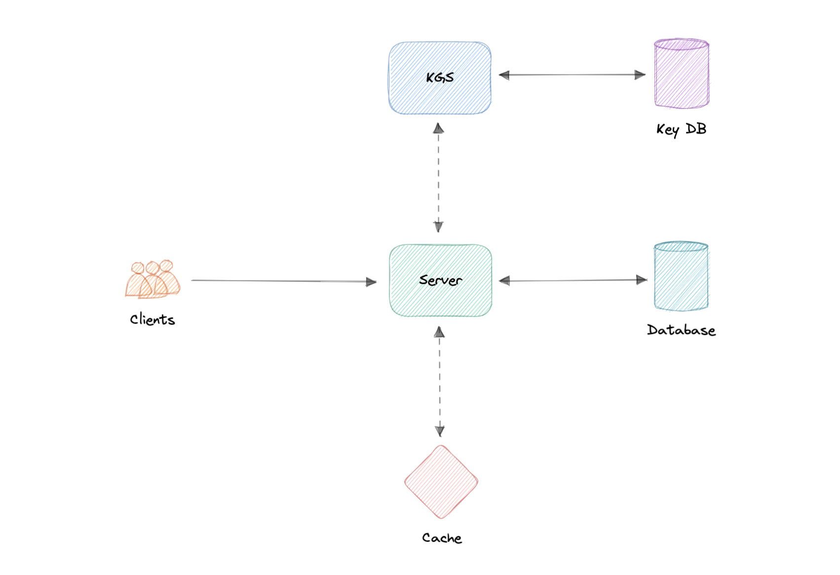
Here’s how it works:
Creating a new URL
- When a user creates a new URL, our API server requests a new unique key from the Key Generation Service (KGS).
- Key Generation Service provides a unique key to the API server and marks the key as used.
- API server writes the new URL entry to the database and cache.
- Our service returns an HTTP 201 (Created) response to the user.
Accessing a URL
- When a client navigates to a certain short URL, the request is sent to the API servers.
- The request first hits the cache, and if the entry is not found there then it is retrieved from the database and an HTTP 301 (Redirect) is issued to the original URL.
- If the key is still not found in the database, an HTTP 404 (Not found) error is sent to the user.
Detailed design
It’s time to discuss the finer details of our design.
Data Partitioning
To scale out our databases we will need to partition our data. Horizontal partitioning (aka Sharding) can be a good first step. We can use partitions schemes such as:
- Hash-Based Partitioning
- List-Based Partitioning
- Range Based Partitioning
- Composite Partitioning
The above approaches can still cause uneven data and load distribution, we can solve this using Consistent hashing.
For more details, refer to Sharding and Consistent Hashing.
Database cleanup
This is more of a maintenance step for our services and depends on whether we keep the expired entries or remove them. If we do decide to remove expired entries, we can approach this in two different ways:
Active cleanup
In active cleanup, we will run a separate cleanup service which will periodically remove expired links from our storage and cache. This will be a very lightweight service like a cron job.
Passive cleanup
For passive cleanup, we can remove the entry when a user tries to access an expired link. This can ensure a lazy cleanup of our database and cache.
Cache
Now let us talk about caching.
Which cache eviction policy to use?
As we discussed before, we can use solutions like Redis or Memcached and cache 20% of the daily traffic but what kind of cache eviction policy would best fit our needs?
Least Recently Used (LRU) can be a good policy for our system. In this policy, we discard the least recently used key first.
How to handle cache miss?
Whenever there is a cache miss, our servers can hit the database directly and update the cache with the new entries.
Metrics and Analytics
Recording analytics and metrics is one of our extended requirements. We can store and update metadata like visitor’s country, platform, the number of views, etc alongside the URL entry in our database.
Security
For security, we can introduce private URLs and authorization. A separate table can be used to store user ids that have permission to access a specific URL. If a user does not have proper permissions, we can return an HTTP 401 (Unauthorized) error.
We can also use an API Gateway as they can support capabilities like authorization, rate limiting, and load balancing out of the box.
Identify and resolve bottlenecks
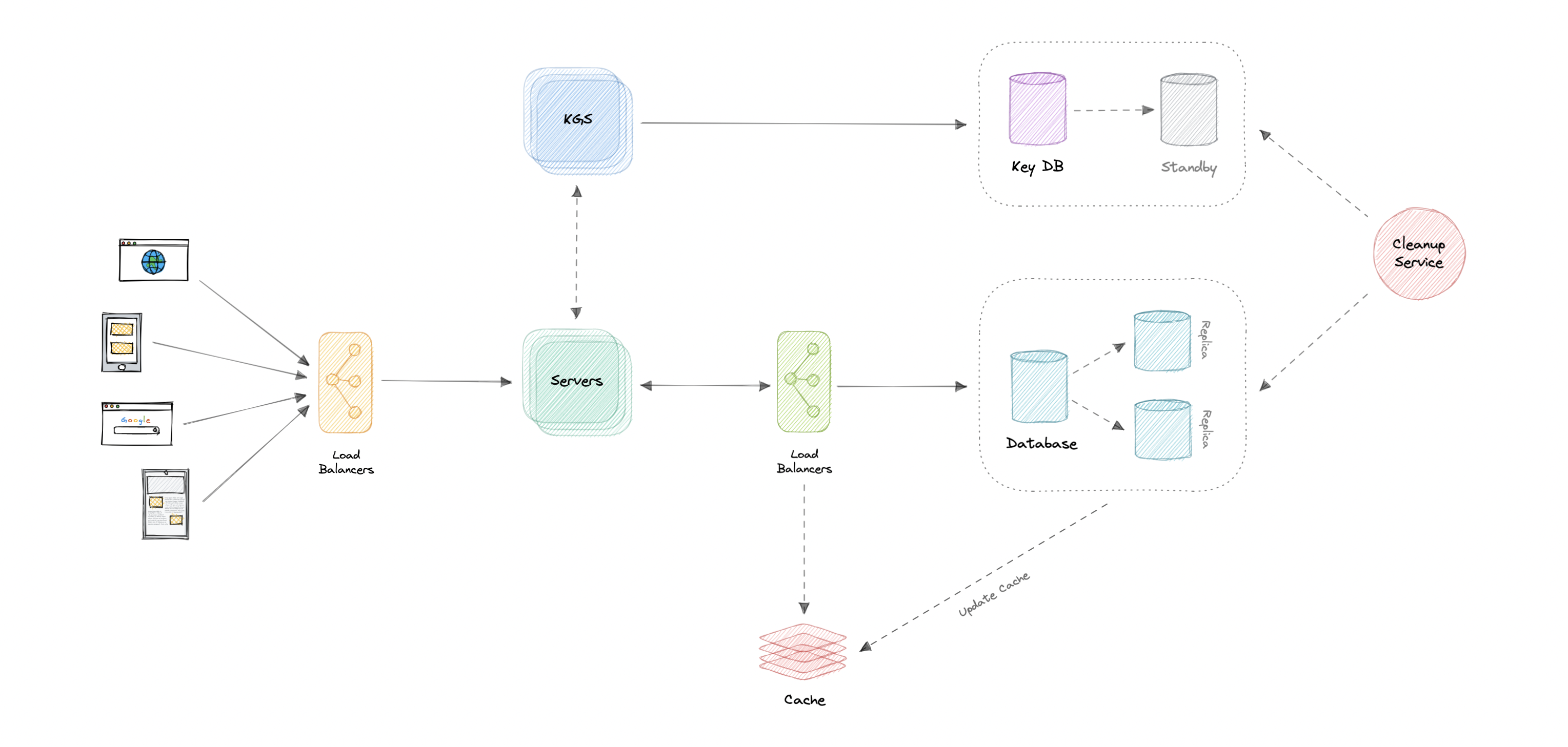
Let us identify and resolve bottlenecks such as single points of failure in our design:
- “What if the API service or Key Generation Service crashes?”
- “How will we distribute our traffic between our components?”
- “How can we reduce the load on our database?”
- “What if the key database used by KGS fails?”
- “How to improve the availability of our cache?”
To make our system more resilient we can do the following:
- Running multiple instances of our Servers and Key Generation Service.
- Introducing load balancers between clients, servers, databases, and cache servers.
- Using multiple read replicas for our database as it’s a read-heavy system.
- Standby replica for our key database in case it fails.
- Multiple instances and replicas for our distributed cache.
Let’s design a WhatsApp like instant messaging service, similar to services like WhatsApp, Facebook Messenger, and WeChat.
What is WhatsApp?
WhatsApp is a chat application that provides instant messaging services to its users. It is one of the most used mobile applications on the planet connecting over 2 billion users in 180+ countries. WhatsApp is also available on the web.
Requirements
Our system should meet the following requirements:
Functional requirements
- Should support one-on-one chat.
- Group chats (max 100 people).
- Should support file sharing (image, video, etc.).
Non-functional requirements
- High availability with minimal latency.
- The system should be scalable and efficient.
Extended requirements
- Sent, Delivered, and Read receipts of the messages.
- Show the last seen time of users.
- Push notifications.
Estimation and Constraints
Let’s start with the estimation and constraints.
Note: Make sure to check any scale or traffic-related assumptions with your interviewer.
Traffic
Let us assume we have 50 million daily active users (DAU) and on average each user sends at least 10 messages to 4 different people every day. This gives us 2 billion messages per day.
\[50 \space million \times 20 \space messages = 2 \space billion/day\]Messages can also contain media such as images, videos, or other files. We can assume that 5 percent of messages are media files shared by the users, which gives us additional 200 million files we would need to store.
\[5 \space percent \times 2 \space billion = 200 \space million/day\]What would be Requests Per Second (RPS) for our system?
2 billion requests per day translate into 24K requests per second.
\[\frac{2 \space billion}{(24 \space hrs \times 3600 \space seconds)} = \sim 24K \space requests/second\]Storage
If we assume each message on average is 100 bytes, we will require about 200 GB of database storage every day.
\[2 \space billion \times 100 \space bytes = \sim 200 \space GB/day\]As per our requirements, we also know that around 5 percent of our daily messages (100 million) are media files. If we assume each file is 50 KB on average, we will require 10 TB of storage every day.
\[100 \space million \times 100 \space KB = 10 \space TB/day\]And for 10 years, we will require about 38 PB of storage.
\[(10 \space TB + 0.2 \space TB) \times 10 \space years \times 365 \space days = \sim 38 \space PB\]Bandwidth
As our system is handling 10.2 TB of ingress every day, we will require a minimum bandwidth of around 120 MB per second.
\[\frac{10.2 \space TB}{(24 \space hrs \times 3600 \space seconds)} = \sim 120 \space MB/second\]High-level estimate
Here is our high-level estimate:
| Type | Estimate |
|---|---|
| Daily active users (DAU) | 50 million |
| Requests per second (RPS) | 24K/s |
| Storage (per day) | ~10.2 TB |
| Storage (10 years) | ~38 PB |
| Bandwidth | ~120 MB/s |
Data model design
This is the general data model which reflects our requirements.
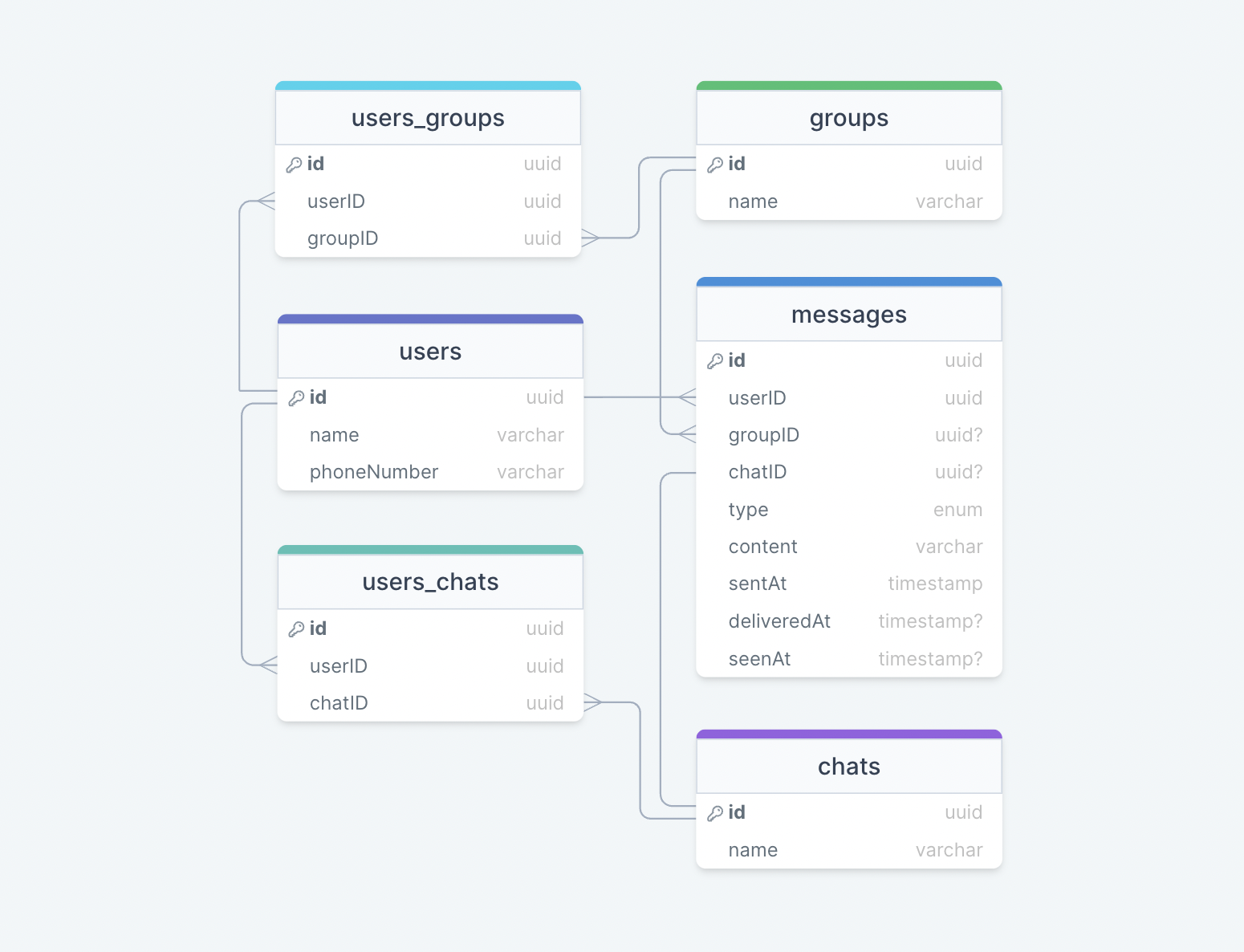
We have the following tables:
users
This table will contain a user’s information such as name, phoneNumber, and other details.
messages
As the name suggests, this table will store messages with properties such as type (text, image, video, etc.), content, and timestamps for message delivery. The message will also have a corresponding chatID or groupID.
chats
This table basically represents a private chat between two users and can contain multiple messages.
users_chats
This table maps users and chats as multiple users can have multiple chats (N:M relationship) and vice versa.
groups
This table represents a group between multiple users.
users_groups
This table maps users and groups as multiple users can be a part of multiple groups (N:M relationship) and vice versa.
What kind of database should we use?
While our data model seems quite relational, we don’t necessarily need to store everything in a single database, as this can limit our scalability and quickly become a bottleneck.
We will split the data between different services each having ownership over a particular table. Then we can use a relational database such as PostgreSQL or a distributed NoSQL database such as Apache Cassandra for our use case.
API design
Let us do a basic API design for our services:
Get all chats or groups
This API will get all chats or groups for a given userID.
getAll(userID: UUID): Chat[] | Group[]
Parameters
User ID (UUID): ID of the current user.
Returns
Result (Chat[] | Group[]): All the chats and groups the user is a part of.
Get messages
Get all messages for a user given the channelID (chat or group id).
getMessages(userID: UUID, channelID: UUID): Message[]
Parameters
User ID (UUID): ID of the current user.
Channel ID (UUID): ID of the channel (chat or group) from which messages need to be retrieved.
Returns
Messages (Message[]): All the messages in a given chat or group.
Send message
Send a message from a user to a channel (chat or group).
sendMessage(userID: UUID, channelID: UUID, message: Message): boolean
Parameters
User ID (UUID): ID of the current user.
Channel ID (UUID): ID of the channel (chat or group) user wants to send a message to.
Message (Message): The message (text, image, video, etc.) that the user wants to send.
Returns
Result (boolean): Represents whether the operation was successful or not.
Join or leave a channel
Allows the user to join or leave a channel (chat or group).
joinGroup(userID: UUID, channelID: UUID): boolean
leaveGroup(userID: UUID, channelID: UUID): boolean
Parameters
User ID (UUID): ID of the current user.
Channel ID (UUID): ID of the channel (chat or group) the user wants to join or leave.
Returns
Result (boolean): Represents whether the operation was successful or not.
High-level design
Now let us do a high-level design of our system.
Architecture
We will be using microservices architecture since it will make it easier to horizontally scale and decouple our services. Each service will have ownership of its own data model. Let’s try to divide our system into some core services.
User Service
This is an HTTP-based service that handles user-related concerns such as authentication and user information.
Chat Service
The chat service will use WebSockets and establish connections with the client to handle chat and group message-related functionality. We can also use cache to keep track of all the active connections sort of like sessions which will help us determine if the user is online or not.
Notification Service
This service will simply send push notifications to the users. It will be discussed in detail separately.
Presence Service
The presence service will keep track of the last seen status of all users. It will be discussed in detail separately.
Media service
This service will handle the media (images, videos, files, etc.) uploads. It will be discussed in detail separately.
What about inter-service communication and service discovery?
Since our architecture is microservices-based, services will be communicating with each other as well. Generally, REST or HTTP performs well but we can further improve the performance using gRPC which is more lightweight and efficient.
Service discovery is another thing we will have to take into account. We can also use a service mesh that enables managed, observable, and secure communication between individual services.
Note: Learn more about REST, GraphQL, gRPC and how they compare with each other.
Real-time messaging
How do we efficiently send and receive messages? We have two different options:
Pull model
The client can periodically send an HTTP request to servers to check if there are any new messages. This can be achieved via something like Long polling.
Push model
The client opens a long-lived connection with the server and once new data is available it will be pushed to the client. We can use WebSockets or Server-Sent Events (SSE) for this.
The pull model approach is not scalable as it will create unnecessary request overhead on our servers and most of the time the response will be empty, thus wasting our resources. To minimize latency, using the push model with WebSockets is a better choice because then we can push data to the client once it’s available without any delay given the connection is open with the client. Also, WebSockets provide full-duplex communication, unlike Server-Sent Events (SSE) which are only unidirectional.
Note: Learn more about Long polling, WebSockets, Server-Sent Events (SSE).
Last seen
To implement the last seen functionality, we can use a heartbeat mechanism, where the client can periodically ping the servers indicating its liveness. Since this needs to be as low overhead as possible, we can store the last active timestamp in the cache as follows:
| Key | Value |
|---|---|
| User A | 2022-07-01T14:32:50 |
| User B | 2022-07-05T05:10:35 |
| User C | 2022-07-10T04:33:25 |
This will give us the last time the user was active. This functionality will be handled by the presence service combined with Redis or Memcached as our cache.
Another way to implement this is to track the latest action of the user, once the last activity crosses a certain threshold, such as “user hasn’t performed any action in the last 30 seconds”, we can show the user as offline and last seen with the last recorded timestamp. This will be more of a lazy update approach and might benefit us over heartbeat in certain cases.
Notifications
Once a message is sent in a chat or a group, we will first check if the recipient is active or not, we can get this information by taking the user’s active connection and last seen into consideration.
If the recipient is not active, the chat service will add an event to a message queue with additional metadata such as the client’s device platform which will be used to route the notification to the correct platform later on.
The notification service will then consume the event from the message queue and forward the request to Firebase Cloud Messaging (FCM) or Apple Push Notification Service (APNS) based on the client’s device platform (Android, iOS, web, etc). We can also add support for email and SMS.
Why are we using a message queue?
Since most message queues provide best-effort ordering which ensures that messages are generally delivered in the same order as they’re sent and that a message is delivered at least once which is an important part of our service functionality.
While this seems like a classic publish-subscribe use case, it is actually not as mobile devices and browsers each have their own way of handling push notifications. Usually, notifications are handled externally via Firebase Cloud Messaging (FCM) or Apple Push Notification Service (APNS) unlike message fan-out which we commonly see in backend services. We can use something like Amazon SQS or RabbitMQ to support this functionality.
Read receipts
Handling read receipts can be tricky, for this use case we can wait for some sort of Acknowledgment (ACK) from the client to determine if the message was delivered and update the corresponding deliveredAt field. Similarly, we will mark message the message seen once the user opens the chat and update the corresponding seenAt timestamp field.
Design
Now that we have identified some core components, let’s do the first draft of our system design.
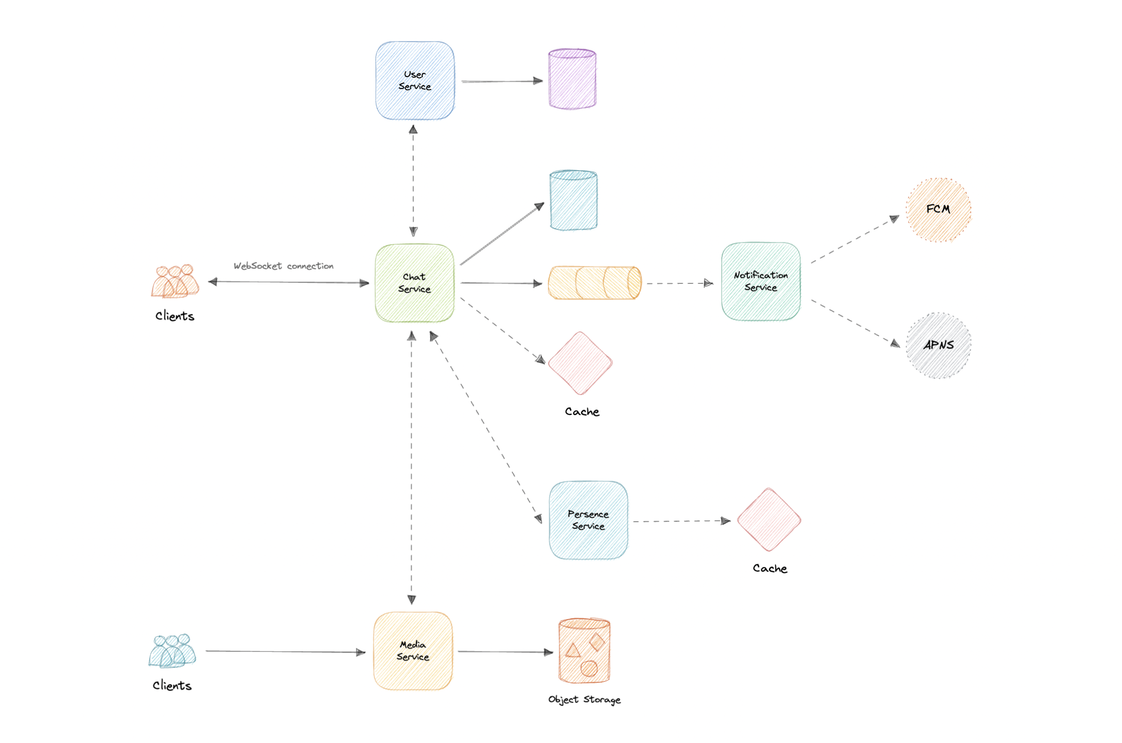
Detailed design
It’s time to discuss our design decisions in detail.
Data Partitioning
To scale out our databases we will need to partition our data. Horizontal partitioning (aka Sharding) can be a good first step. We can use partitions schemes such as:
- Hash-Based Partitioning
- List-Based Partitioning
- Range Based Partitioning
- Composite Partitioning
The above approaches can still cause uneven data and load distribution, we can solve this using Consistent hashing.
For more details, refer to Sharding and Consistent Hashing.
Caching
In a messaging application, we have to be careful about using cache as our users expect the latest data, but many users will be requesting the same messages, especially in a group chat. So, to prevent usage spikes from our resources we can cache older messages.
Some group chats can have thousands of messages and sending that over the network will be really inefficient, to improve efficiency we can add pagination to our system APIs. This decision will be helpful for users with limited network bandwidth as they won’t have to retrieve old messages unless requested.
Which cache eviction policy to use?
We can use solutions like Redis or Memcached and cache 20% of the daily traffic but what kind of cache eviction policy would best fit our needs?
Least Recently Used (LRU) can be a good policy for our system. In this policy, we discard the least recently used key first.
How to handle cache miss?
Whenever there is a cache miss, our servers can hit the database directly and update the cache with the new entries.
For more details, refer to Caching.
Media access and storage
As we know, most of our storage space will be used for storing media files such as images, videos, or other files. Our media service will be handling both access and storage of the user media files.
But where can we store files at scale? Well, object storage is what we’re looking for. Object stores break data files up into pieces called objects. It then stores those objects in a single repository, which can be spread out across multiple networked systems. We can also use distributed file storage such as HDFS or GlusterFS.
Fun fact: WhatsApp deletes media on its servers once it has been downloaded by the user.
We can use object stores like Amazon S3, Azure Blob Storage, or Google Cloud Storage for this use case.
Content Delivery Network (CDN)
Content Delivery Network (CDN) increases content availability and redundancy while reducing bandwidth costs. Generally, static files such as images, and videos are served from CDN. We can use services like Amazon CloudFront or Cloudflare CDN for this use case.
API gateway
Since we will be using multiple protocols like HTTP, WebSocket, TCP/IP, deploying multiple L4 (transport layer) or L7 (application layer) type load balancers separately for each protocol will be expensive. Instead, we can use an API Gateway that supports multiple protocols without any issues.
API Gateway can also offer other features such as authentication, authorization, rate limiting, throttling, and API versioning which will improve the quality of our services.
We can use services like Amazon API Gateway or Azure API Gateway for this use case.
Identify and resolve bottlenecks
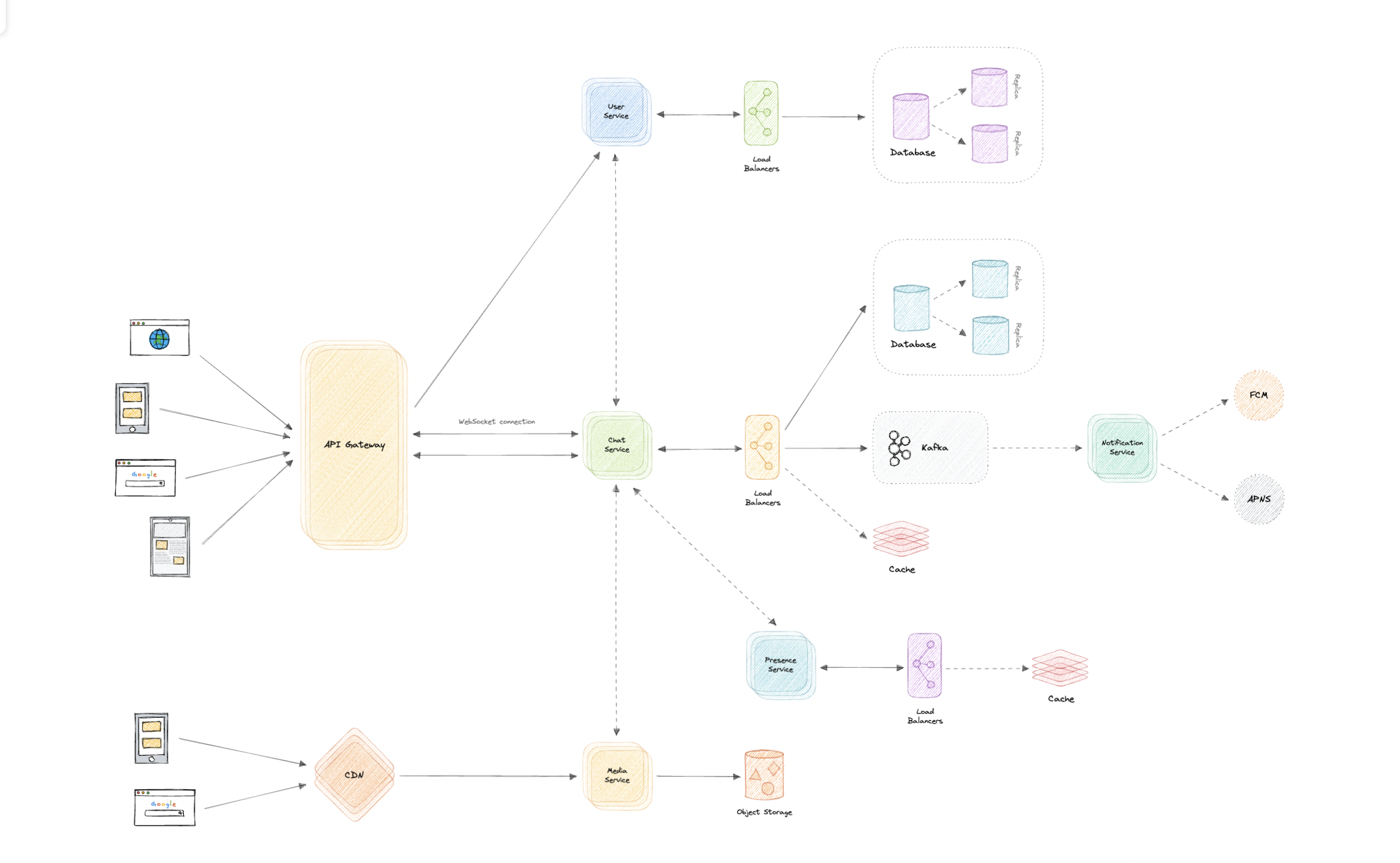
Let us identify and resolve bottlenecks such as single points of failure in our design:
- “What if one of our services crashes?”
- “How will we distribute our traffic between our components?”
- “How can we reduce the load on our database?”
- “How to improve the availability of our cache?”
- “Wouldn’t API Gateway be a single point of failure?”
- “How can we make our notification system more robust?”
- “How can we reduce media storage costs”?
- “Does chat service has too much responsibility?”
To make our system more resilient we can do the following:
- Running multiple instances of each of our services.
- Introducing load balancers between clients, servers, databases, and cache servers.
- Using multiple read replicas for our databases.
- Multiple instances and replicas for our distributed cache.
- We can have a standby replica of our API Gateway.
- Exactly once delivery and message ordering is challenging in a distributed system, we can use a dedicated message broker such as Apache Kafka or NATS to make our notification system more robust.
- We can add media processing and compression capabilities to the media service to compress large files similar to WhatsApp which will save a lot of storage space and reduce cost.
- We can create a group service separate from the chat service to further decouple our services.
Let’s design a Twitter like social media service, similar to services like Facebook, Instagram, etc.
What is Twitter?
Twitter is a social media service where users can read or post short messages (up to 280 characters) called tweets. It is available on the web and mobile platforms such as Android and iOS.
Requirements
Our system should meet the following requirements:
Functional requirements
- Should be able to post new tweets (can be text, image, video, etc.).
- Should be able to follow other users.
- Should have a newsfeed feature consisting of tweets from the people the user is following.
- Should be able to search tweets.
Non-Functional requirements
- High availability with minimal latency.
- The system should be scalable and efficient.
Extended requirements
- Metrics and analytics.
- Retweet functionality.
- Favorite tweets.
Estimation and Constraints
Let’s start with the estimation and constraints.
Note: Make sure to check any scale or traffic-related assumptions with your interviewer.
Traffic
This will be a read-heavy system, let us assume we have 1 billion total users with 200 million daily active users (DAU), and on average each user tweets 5 times a day. This gives us 1 billion tweets per day.
\[200 \space million \times 5 \space messages = 1 \space billion/day\]Tweets can also contain media such as images, or videos. We can assume that 10 percent of tweets are media files shared by the users, which gives us additional 100 million files we would need to store.
\[10 \space percent \times 1 \space billion = 100 \space million/day\]What would be Requests Per Second (RPS) for our system?
1 billion requests per day translate into 12K requests per second.
\[\frac{1 \space billion}{(24 \space hrs \times 3600 \space seconds)} = \sim 12K \space requests/second\]Storage
If we assume each message on average is 100 bytes, we will require about 100 GB of database storage every day.
\[1 \space billion \times 100 \space bytes = \sim 100 \space GB/day\]We also know that around 10 percent of our daily messages (100 million) are media files per our requirements. If we assume each file is 50 KB on average, we will require 5 TB of storage every day.
\[100 \space million \times 100 \space KB = 5 \space TB/day\]And for 10 years, we will require about 19 PB of storage.
\[(5 \space TB + 0.1 \space TB) \times 365 \space days \times 10 \space years = \sim 19 \space PB\]Bandwidth
As our system is handling 5.1 TB of ingress every day, we will require a minimum bandwidth of around 60 MB per second.
\[\frac{5.1 \space TB}{(24 \space hrs \times 3600 \space seconds)} = \sim 60 \space MB/second\]High-level estimate
Here is our high-level estimate:
| Type | Estimate |
|---|---|
| Daily active users (DAU) | 100 million |
| Requests per second (RPS) | 12K/s |
| Storage (per day) | ~5.1 TB |
| Storage (10 years) | ~19 PB |
| Bandwidth | ~60 MB/s |
Data model design
This is the general data model which reflects our requirements.
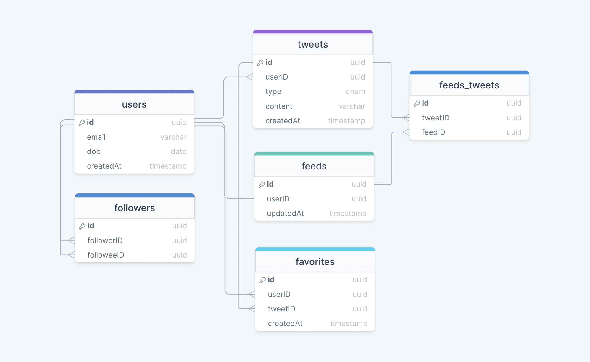
We have the following tables:
users
This table will contain a user’s information such as name, email, dob, and other details.
tweets
As the name suggests, this table will store tweets and their properties such as type (text, image, video, etc.), content, etc. We will also store the corresponding userID.
favorites
This table maps tweets with users for the favorite tweets functionality in our application.
followers
This table maps the followers and followees as users can follow each other (N:M relationship).
feeds
This table stores feed properties with the corresponding userID.
feeds_tweets
This table maps tweets and feed (N:M relationship).
What kind of database should we use?
While our data model seems quite relational, we don’t necessarily need to store everything in a single database, as this can limit our scalability and quickly become a bottleneck.
We will split the data between different services each having ownership over a particular table. Then we can use a relational database such as PostgreSQL or a distributed NoSQL database such as Apache Cassandra for our use case.
API design
Let us do a basic API design for our services:
Post a tweet
This API will allow the user to post a tweet on the platform.
postTweet(userID: UUID, content: string, mediaURL?: string): boolean
Parameters
User ID (UUID): ID of the user.
Content (string): Contents of the tweet.
Media URL (string): URL of the attached media (optional).
Returns
Result (boolean): Represents whether the operation was successful or not.
Follow or unfollow a user
This API will allow the user to follow or unfollow another user.
follow(followerID: UUID, followeeID: UUID): boolean
unfollow(followerID: UUID, followeeID: UUID): boolean
Parameters
Follower ID (UUID): ID of the current user.
Followee ID (UUID): ID of the user we want to follow or unfollow.
Media URL (string): URL of the attached media (optional).
Returns
Result (boolean): Represents whether the operation was successful or not.
Get newsfeed
This API will return all the tweets to be shown within a given newsfeed.
getNewsfeed(userID: UUID): Tweet[]
Parameters
User ID (UUID): ID of the user.
Returns
Tweets (Tweet[]): All the tweets to be shown within a given newsfeed.
High-level design
Now let us do a high-level design of our system.
Architecture
We will be using microservices architecture since it will make it easier to horizontally scale and decouple our services. Each service will have ownership of its own data model. Let’s try to divide our system into some core services.
User Service
This service handles user-related concerns such as authentication and user information.
Newsfeed Service
This service will handle the generation and publishing of user newsfeeds. It will be discussed in detail separately.
Tweet Service
The tweet service will handle tweet-related use cases such as posting a tweet, favorites, etc.
Search Service
The service is responsible for handling search-related functionality. It will be discussed in detail separately.
Media service
This service will handle the media (images, videos, files, etc.) uploads. It will be discussed in detail separately.
Notification Service
This service will simply send push notifications to the users.
Analytics Service
This service will be used for metrics and analytics use cases.
What about inter-service communication and service discovery?
Since our architecture is microservices-based, services will be communicating with each other as well. Generally, REST or HTTP performs well but we can further improve the performance using gRPC which is more lightweight and efficient.
Service discovery is another thing we will have to take into account. We can also use a service mesh that enables managed, observable, and secure communication between individual services.
Note: Learn more about REST, GraphQL, gRPC and how they compare with each other.
Newsfeed
When it comes to the newsfeed, it seems easy enough to implement, but there are a lot of things that can make or break this feature. So, let’s divide our problem into two parts:
Generation
Let’s assume we want to generate the feed for user A, we will perform the following steps:
- Retrieve the IDs of all the users and entities (hashtags, topics, etc.) user A follows.
- Fetch the relevant tweets for each of the retrieved IDs.
- Use a ranking algorithm to rank the tweets based on parameters such as relevance, time, engagement, etc.
- Return the ranked tweets data to the client in a paginated manner.
Feed generation is an intensive process and can take quite a lot of time, especially for users following a lot of people. To improve the performance, the feed can be pre-generated and stored in the cache, then we can have a mechanism to periodically update the feed and apply our ranking algorithm to the new tweets.
Publishing
Publishing is the step where the feed data is pushed according to each specific user. This can be a quite heavy operation, as a user may have millions of friends or followers. To deal with this, we have three different approaches:
- Pull Model (or Fan-out on load)
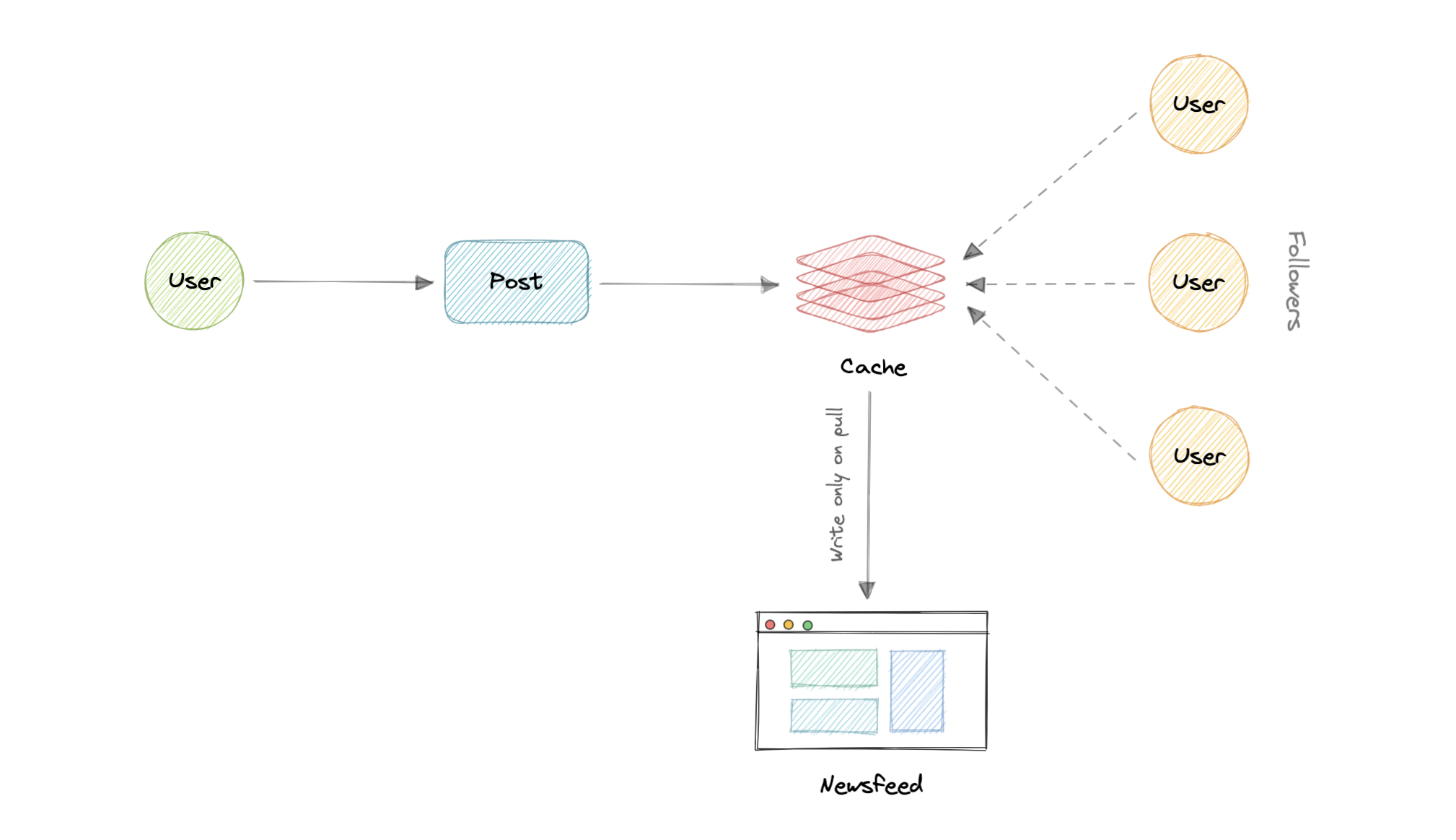
When a user creates a tweet, and a follower reloads their newsfeed, the feed is created and stored in memory. The most recent feed is only loaded when the user requests it. This approach reduces the number of write operations on our database.
The downside of this approach is that the users will not be able to view recent feeds unless they “pull” the data from the server, which will increase the number of read operations on the server.
- Push Model (or Fan-out on write)
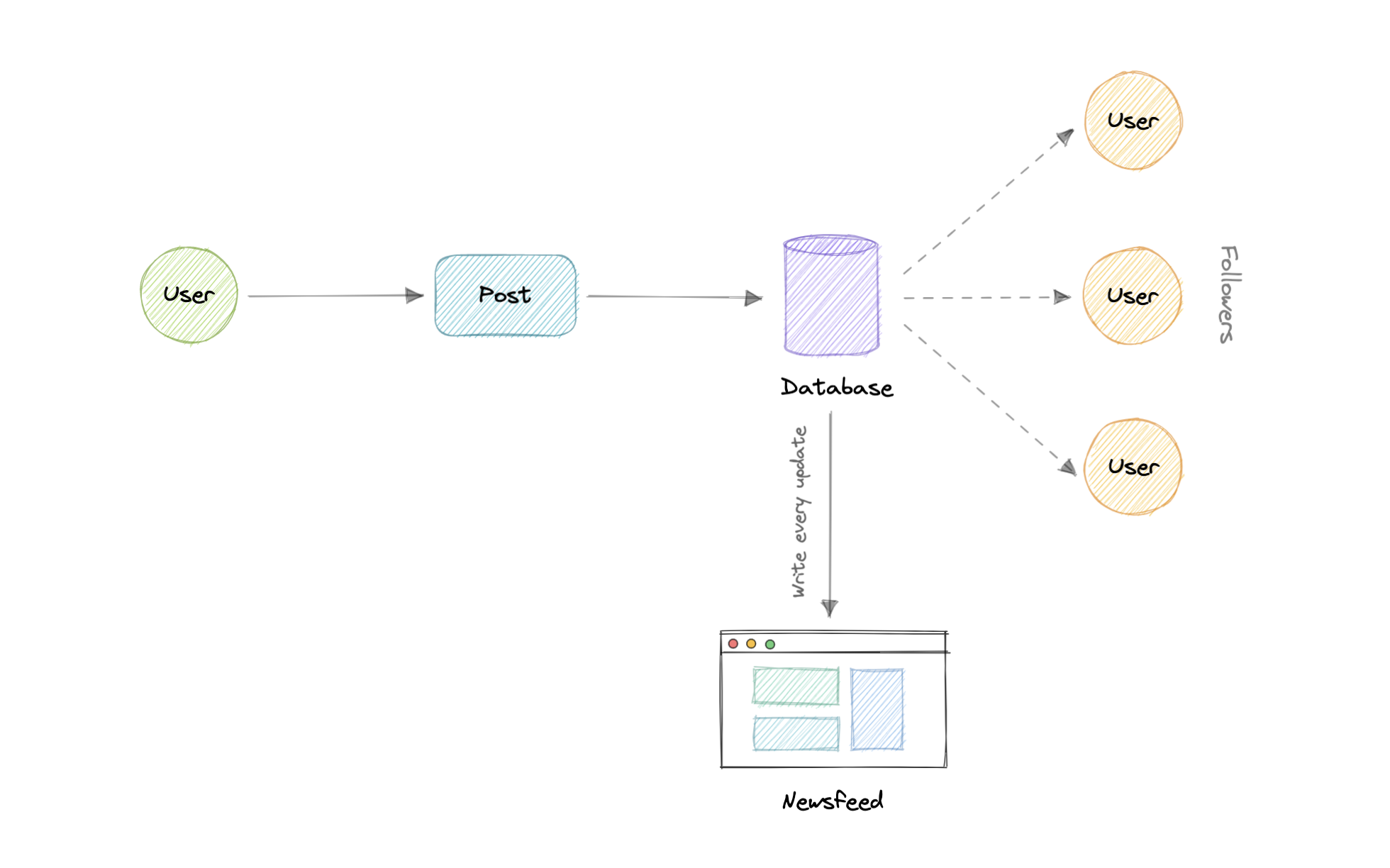
In this model, once a user creates a tweet, it is “pushed” to all the follower’s feeds immediately. This prevents the system from having to go through a user’s entire followers list to check for updates.
However, the downside of this approach is that it would increase the number of write operations on the database.
- Hybrid Model
A third approach is a hybrid model between the pull and push model. It combines the beneficial features of the above two models and tries to provide a balanced approach between the two.
The hybrid model allows only users with a lesser number of followers to use the push model and for users with a higher number of followers celebrities, the pull model will be used.
Ranking Algorithm
As we discussed, we will need a ranking algorithm to rank each tweet according to its relevance to each specific user.
For example, Facebook used to utilize an EdgeRank algorithm, here, the rank of each feed item is described by:
\[Rank = Affinity \times Weight \times Decay\]Where,
Affinity: is the “closeness” of the user to the creator of the edge. If a user frequently likes, comments, or messages the edge creator, then the value of affinity will be higher, resulting in a higher rank for the post.
Weight: is the value assigned according to each edge. A comment can have a higher weightage than likes, and thus a post with more comments is more likely to get a higher rank.
Decay: is the measure of the creation of the edge. The older the edge, the lesser will be the value of decay and eventually the rank.
Nowadays, algorithms are much more complex and ranking is done using machine learning models which can take thousands of factors into consideration.
Retweets
Retweets are one of our extended requirements. To implement this feature we can simply create a new tweet with the user id of the user retweeting the original tweet and then modify the type enum and content property of the new tweet to link it with the original tweet.
For example, the type enum property can be of type tweet, similar to text, video, etc and content can be the id of the original tweet. Here the first row indicates the original tweet while the second row is how we can represent a retweet.
| id | userID | type | content | createdAt |
|---|---|---|---|---|
| ad34-291a-45f6-b36c | 7a2c-62c4-4dc8-b1bb | text | Hey, this is my first tweet… | 1658905644054 |
| f064-49ad-9aa2-84a6 | 6aa2-2bc9-4331-879f | tweet | ad34-291a-45f6-b36c | 1658906165427 |
This is a very basic implementation, to improve this we can create a separate table itself to store retweets.
Search
Sometimes traditional DBMS are not performant enough, we need something which allows us to store, search, and analyze huge volumes of data quickly and in near real-time and give results within milliseconds. Elasticsearch can help us with this use case.
Elasticsearch is a distributed, free and open search and analytics engine for all types of data, including textual, numerical, geospatial, structured, and unstructured. It is built on top of Apache Lucene.
How do we identify trending topics?
Trending functionality will be based on top of the search functionality. We can cache the most frequently searched queries, hashtags, and topics in the last N seconds and update them every M seconds using some sort of batch job mechanism. Our ranking algorithm can also be applied to the trending topics to give them more weight and personalize them for the user.
Notifications
Push notifications are an integral part of any social media platform. We can use a message queue or a message broker such as Apache Kafka with the notification service to dispatch requests to Firebase Cloud Messaging (FCM) or Apple Push Notification Service (APNS) which will handle the delivery of the push notifications to user devices.
For more details, refer to the WhatsApp system design where we discuss push notifications.
Detailed design
It’s time to discuss our design decisions in detail.
Data Partitioning
To scale out our databases we will need to partition our data. Horizontal partitioning (aka Sharding) can be a good first step. We can use partitions schemes such as:
- Hash-Based Partitioning
- List-Based Partitioning
- Range Based Partitioning
- Composite Partitioning
The above approaches can still cause uneven data and load distribution, we can solve this using Consistent hashing.
For more details, refer to Sharding and Consistent Hashing.
Mutual friends
For mutual friends, we can build a social graph for every user. Each node in the graph will represent a user and a directional edge will represent followers and followees. After that, we can traverse the followers of a user to find and suggest a mutual friend. This would require a graph database such as Neo4j and ArangoDB.
This is a pretty simple algorithm, to improve our suggestion accuracy, we will need to incorporate a recommendation model which uses machine learning as part of our algorithm.
Metrics and Analytics
Recording analytics and metrics is one of our extended requirements. As we will be using Apache Kafka to publish all sorts of events, we can process these events and run analytics on the data using Apache Spark which is an open-source unified analytics engine for large-scale data processing.
Caching
In a social media application, we have to be careful about using cache as our users expect the latest data. So, to prevent usage spikes from our resources we can cache the top 20% of the tweets.
To further improve efficiency we can add pagination to our system APIs. This decision will be helpful for users with limited network bandwidth as they won’t have to retrieve old messages unless requested.
Which cache eviction policy to use?
We can use solutions like Redis or Memcached and cache 20% of the daily traffic but what kind of cache eviction policy would best fit our needs?
Least Recently Used (LRU) can be a good policy for our system. In this policy, we discard the least recently used key first.
How to handle cache miss?
Whenever there is a cache miss, our servers can hit the database directly and update the cache with the new entries.
For more details, refer to Caching.
Media access and storage
As we know, most of our storage space will be used for storing media files such as images, videos, or other files. Our media service will be handling both access and storage of the user media files.
But where can we store files at scale? Well, object storage is what we’re looking for. Object stores break data files up into pieces called objects. It then stores those objects in a single repository, which can be spread out across multiple networked systems. We can also use distributed file storage such as HDFS or GlusterFS.
Content Delivery Network (CDN)
Content Delivery Network (CDN) increases content availability and redundancy while reducing bandwidth costs. Generally, static files such as images, and videos are served from CDN. We can use services like Amazon CloudFront or Cloudflare CDN for this use case.
Identify and resolve bottlenecks
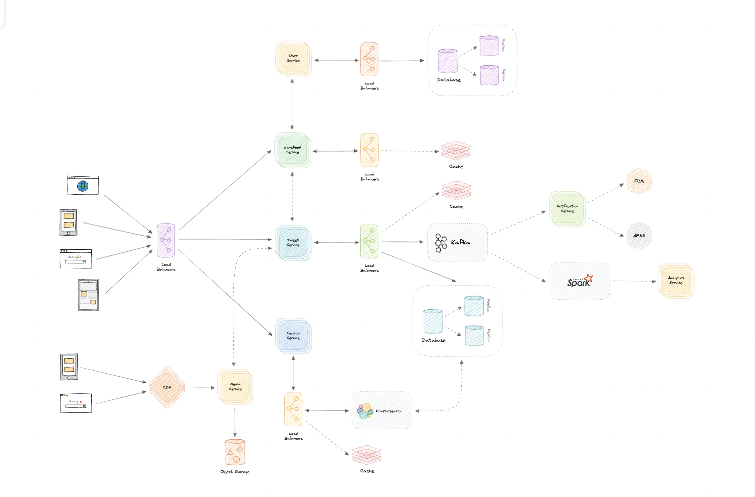
Let us identify and resolve bottlenecks such as single points of failure in our design:
- “What if one of our services crashes?”
- “How will we distribute our traffic between our components?”
- “How can we reduce the load on our database?”
- “How to improve the availability of our cache?”
- “How can we make our notification system more robust?”
- “How can we reduce media storage costs”?
To make our system more resilient we can do the following:
- Running multiple instances of each of our services.
- Introducing load balancers between clients, servers, databases, and cache servers.
- Using multiple read replicas for our databases.
- Multiple instances and replicas for our distributed cache.
- Exactly once delivery and message ordering is challenging in a distributed system, we can use a dedicated message broker such as Apache Kafka or NATS to make our notification system more robust.
- We can add media processing and compression capabilities to the media service to compress large files which will save a lot of storage space and reduce cost.
Netflix
Let’s design a Netflix like video streaming service, similar to services like Amazon Prime Video, Disney Plus, Hulu, Youtube, Vimeo, etc.
What is Netflix?
Netflix is a subscription-based streaming service that allows its members to watch TV shows and movies on an internet-connected device. It is available on platforms such as the Web, iOS, Android, TV, etc.
Requirements
Our system should meet the following requirements:
Functional requirements
- Users should be able to stream and share videos.
- The content team (or users in YouTube’s case) should be able to upload new videos (movies, tv shows episodes, and other content).
- Users should be able to search for videos using titles or tags.
- Users should be able to comment on a video similar to YouTube.
Non-Functional requirements
- High availability with minimal latency.
- High reliability, no uploads should be lost.
- The system should be scalable and efficient.
Extended requirements
- Certain content should be geo-blocked.
- Resume video playback from the point user left off.
- Record metrics and analytics of videos.
Estimation and Constraints
Let’s start with the estimation and constraints.
Note: Make sure to check any scale or traffic-related assumptions with your interviewer.
Traffic
This will be a read-heavy system, let us assume we have 1 billion total users with 200 million daily active users (DAU), and on average each user watches 5 videos a day. This gives us 1 billion videos watched per day.
\[200 \space million \times 5 \space videos = 1 \space billion/day\]Assuming, a 200:1 read/write ratio, about 50 million videos will be uploaded every day.
What would be Requests Per Second (RPS) for our system?
1 billion requests per day translate into 12K requests per second.
\[\frac{1 \space billion}{(24 \space hrs \times 3600 \space seconds)} = \sim 12K \space requests/second\]Storage
If we assume each video is 100 MB on average, we will require about 5 PB of storage every day.
\[50 \space million \times 100 \space MB = 5 \space PB/day\]And for 10 years, we will require an astounding 18,250 PB of storage.
\[5 \space PB \times 365 \space days \times 10 \space years = \sim 18,250 \space PB\]Bandwidth
As our system is handling 5 PB of ingress every day, we will require a minimum bandwidth of around 58 GB per second.
\[\frac{5 \space PB}{(24 \space hrs \times 3600 \space seconds)} = \sim 58 \space GB/second\]High-level estimate
Here is our high-level estimate:
| Type | Estimate |
|---|---|
| Daily active users (DAU) | 200 million |
| Requests per second (RPS) | 12K/s |
| Storage (per day) | ~5 PB |
| Storage (10 years) | ~18,250 PB |
| Bandwidth | ~58 GB/s |
Data model design
This is the general data model which reflects our requirements.
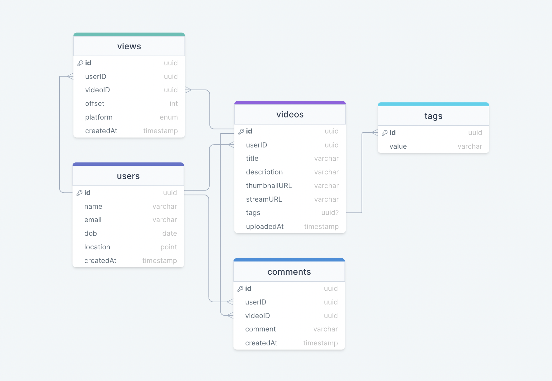
We have the following tables:
users
This table will contain a user’s information such as name, email, dob, and other details.
videos
As the name suggests, this table will store videos and their properties such as title, streamURL, tags, etc. We will also store the corresponding userID.
tags
This table will simply store tags associated with a video.
views
This table helps us to store all the views received on a video.
comments
This table stores all the comments received on a video (like YouTube).
What kind of database should we use?
While our data model seems quite relational, we don’t necessarily need to store everything in a single database, as this can limit our scalability and quickly become a bottleneck.
We will split the data between different services each having ownership over a particular table. Then we can use a relational database such as PostgreSQL or a distributed NoSQL database such as Apache Cassandra for our use case.
API design
Let us do a basic API design for our services:
Upload a video
Given a byte stream, this API enables video to be uploaded to our service.
uploadVideo(title: string, description: string, data: Stream<byte>, tags?: string[]): boolean
Parameters
Title (string): Title of the new video.
Description (string): Description of the new video.
Data (Byte[]): Byte stream of the video data.
Tags (string[]): Tags for the video (optional).
Returns
Result (boolean): Represents whether the operation was successful or not.
Streaming a video
This API allows our users to stream a video with the preferred codec and resolution.
streamVideo(videoID: UUID, codec: Enum<string>, resolution: Tuple<int>, offset?: int): VideoStream
Parameters
Video ID (UUID): ID of the video that needs to be streamed.
Codec (Enum<string>): Required codec of the requested video, such as h.265, h.264, VP9, etc.
Resolution (Tuple<int>): Resolution of the requested video.
Offset (int): Offset of the video stream in seconds to stream data from any point in the video (optional).
Returns
Stream (VideoStream): Data stream of the requested video.
Search for a video
This API will enable our users to search for a video based on its title or tags.
searchVideo(query: string, nextPage?: string): Video[]
Parameters
Query (string): Search query from the user.
Next Page (string): Token for the next page, this can be used for pagination (optional).
Returns
Videos (Video[]): All the videos available for a particular search query.
Add a comment
This API will allow our users to post a comment on a video (like YouTube).
comment(videoID: UUID, comment: string): boolean
Parameters
VideoID (UUID): ID of the video user wants to comment on.
Comment (string): The text content of the comment.
Returns
Result (boolean): Represents whether the operation was successful or not.
High-level design
Now let us do a high-level design of our system.
Architecture
We will be using microservices architecture since it will make it easier to horizontally scale and decouple our services. Each service will have ownership of its own data model. Let’s try to divide our system into some core services.
User Service
This service handles user-related concerns such as authentication and user information.
Stream Service
The tweet service will handle video streaming-related functionality.
Search Service
The service is responsible for handling search-related functionality. It will be discussed in detail separately.
Media service
This service will handle the video uploads and processing. It will be discussed in detail separately.
Analytics Service
This service will be used for metrics and analytics use cases.
What about inter-service communication and service discovery?
Since our architecture is microservices-based, services will be communicating with each other as well. Generally, REST or HTTP performs well but we can further improve the performance using gRPC which is more lightweight and efficient.
Service discovery is another thing we will have to take into account. We can also use a service mesh that enables managed, observable, and secure communication between individual services.
Note: Learn more about REST, GraphQL, gRPC and how they compare with each other.
Video processing
There are so many variables in play when it comes to processing a video. For example, an average data size of two-hour raw 8K footage from a high-end camera can easily be up to 4 TB, thus we need to have some kind of processing to reduce both storage and delivery costs.
Here’s how we can process videos once they’re uploaded by the content team (or users in YouTube’s case) and are queued for processing in our message queue.
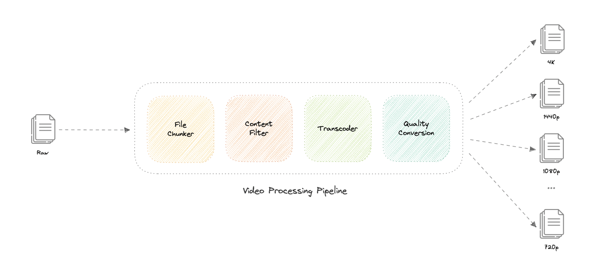
Let’s discuss how this works:
- File Chunker
This is the first step of our processing pipeline. File chunking is the process of splitting a file into smaller pieces called chunks. It can help us eliminate duplicate copies of repeating data on storage, and reduces the amount of data sent over the network by only selecting changed chunks.
Usually, a video file can be split into equal size chunks based on timestamps but Netflix instead splits chunks based on scenes, this slight variation becomes a huge factor for a better user experience as whenever the client requests a chunk from the server, there is a lower chance of interruption as a complete scene will be retrieved.
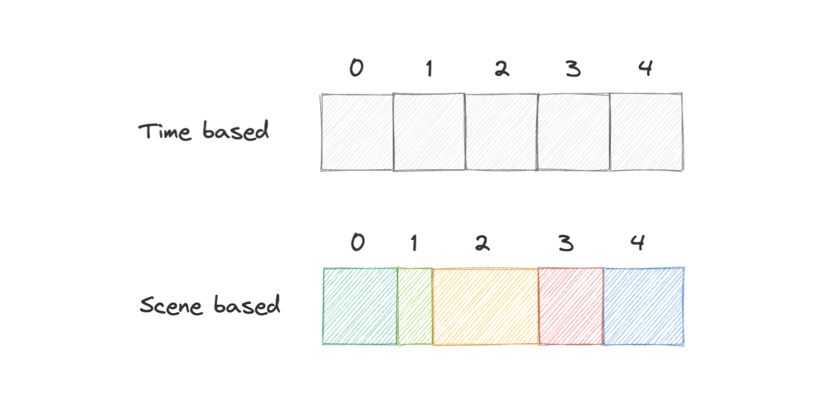
- Content Filter
This step checks if the video adheres to the content policy of the platform, this can be pre-approved in the case of Netflix as per the content rating of the media or can be strictly enforced like YouTube.
This entire step is done by a machine learning model which performs copyright, piracy, and NSFW checks. If issues are found, we can push the task to a dead-letter queue (DLQ) and someone from the moderation team can do further inspection.
- Transcoder
Transcoding is a process in which the original data is decoded to an intermediate uncompressed format, which is then encoded into the target format. This process uses different codecs to perform bitrate adjustment, image downsampling, or re-encoding the media.
This results in a smaller size file and a much more optimized format for the target devices. Standalone solutions such as FFmpeg or cloud-based solutions like AWS Elemental MediaConvert can be used to implement this step of the pipeline.
- Quality Conversion
This is the last step of the processing pipeline and as the name suggests, this step handles the conversion of the transcoded media from the previous step into different resolutions such as 4K, 1440p, 1080p, 720p, etc.
This allows us to fetch the desired quality of the video as per the user’s request, and once the media file finishes processing, it will be uploaded to a distributed file storage such as HDFS, GlusterFS, or an object storage such as Amazon S3 for later retrieval during streaming.
Note: We can add additional steps such as subtitles and thumbnails generation as part of our pipeline.
Why are we using a message queue?
Processing videos as a long-running task makes much more sense, and a message queue also decouples our video processing pipeline from the uploads functionality. We can use something like Amazon SQS or RabbitMQ to support this.
Video streaming
Video streaming is a challenging task from both the client and server perspectives. Moreover, internet connection speeds vary quite a lot between different users. To make sure users don’t re-fetch the same content, we can use a Content Delivery Network (CDN).
Netflix takes this a step further with its Open Connect program. In this approach, they partner with thousands of Internet Service Providers (ISPs) to localize their traffic and deliver their content more efficiently.
What is the difference between Netflix’s Open Connect and a traditional Content Delivery Network (CDN)?
Netflix Open Connect is our purpose-built Content Delivery Network (CDN) responsible for serving Netflix’s video traffic. Around 95% of the traffic globally is delivered via direct connections between Open Connect and the ISPs their customers use to access the internet.
Currently, they have Open Connect Appliances (OCAs) in over 1000 separate locations around the world. In case of issues, Open Connect Appliances (OCAs) can failover, and the traffic can be re-routed to Netflix servers.
Additionally, we can use Adaptive bitrate streaming protocols such as HTTP Live Streaming (HLS) which is designed for reliability and it dynamically adapts to network conditions by optimizing playback for the available speed of the connections.
Lastly, for playing the video from where the user left off (part of our extended requirements), we can simply use the offset property we stored in the views table to retrieve the scene chunk at that particular timestamp and resume the playback for the user.
Searching
Sometimes traditional DBMS are not performant enough, we need something which allows us to store, search, and analyze huge volumes of data quickly and in near real-time and give results within milliseconds. Elasticsearch can help us with this use case.
Elasticsearch is a distributed, free and open search and analytics engine for all types of data, including textual, numerical, geospatial, structured, and unstructured. It is built on top of Apache Lucene.
How do we identify trending content?
Trending functionality will be based on top of the search functionality. We can cache the most frequently searched queries in the last N seconds and update them every M seconds using some sort of batch job mechanism.
Sharing
Sharing content is an important part of any platform, for this, we can have some sort of URL shortener service in place that can generate short URLs for the users to share.
For more details, refer to the URL Shortener system design.
Detailed design
It’s time to discuss our design decisions in detail.
Data Partitioning
To scale out our databases we will need to partition our data. Horizontal partitioning (aka Sharding) can be a good first step. We can use partitions schemes such as:
- Hash-Based Partitioning
- List-Based Partitioning
- Range Based Partitioning
- Composite Partitioning
The above approaches can still cause uneven data and load distribution, we can solve this using Consistent hashing.
For more details, refer to Sharding and Consistent Hashing.
Geo-blocking
Platforms like Netflix and YouTube use Geo-blocking to restrict content in certain geographical areas or countries. This is primarily done due to legal distribution laws that Netflix has to adhere to when they make a deal with the production and distribution companies. In the case of YouTube, this will be controlled by the user during the publishing of the content.
We can determine the user’s location either using their IP or region settings in their profile then use services like Amazon CloudFront which supports a geographic restrictions feature or a geolocation routing policy with Amazon Route53 to restrict the content and re-route the user to an error page if the content is not available in that particular region or country.
Recommendations
Netflix uses a machine learning model which uses the user’s viewing history to predict what the user might like to watch next, an algorithm like Collaborative Filtering can be used.
However, Netflix (like YouTube) uses its own algorithm called Netflix Recommendation Engine which can track several data points such as:
- User profile information like age, gender, and location.
- Browsing and scrolling behavior of the user.
- Time and date a user watched a title.
- The device which was used to stream the content.
- The number of searches and what terms were searched.
For more detail, refer to Netflix recommendation research.
Metrics and Analytics
Recording analytics and metrics is one of our extended requirements. We can capture the data from different services and run analytics on the data using Apache Spark which is an open-source unified analytics engine for large-scale data processing. Additionally, we can store critical metadata in the views table to increase data points within our data.
Caching
In a streaming platform, caching is important. We have to be able to cache as much static media content as possible to improve user experience. We can use solutions like Redis or Memcached but what kind of cache eviction policy would best fit our needs?
Which cache eviction policy to use?
Least Recently Used (LRU) can be a good policy for our system. In this policy, we discard the least recently used key first.
How to handle cache miss?
Whenever there is a cache miss, our servers can hit the database directly and update the cache with the new entries.
For more details, refer to Caching.
Media streaming and storage
As most of our storage space will be used for storing media files such as thumbnails and videos. Per our discussion earlier, the media service will be handling both the upload and processing of media files.
We will use distributed file storage such as HDFS, GlusterFS, or an object storage such as Amazon S3 for storage and streaming of the content.
Content Delivery Network (CDN)
Content Delivery Network (CDN) increases content availability and redundancy while reducing bandwidth costs. Generally, static files such as images, and videos are served from CDN. We can use services like Amazon CloudFront or Cloudflare CDN for this use case.
Identify and resolve bottlenecks
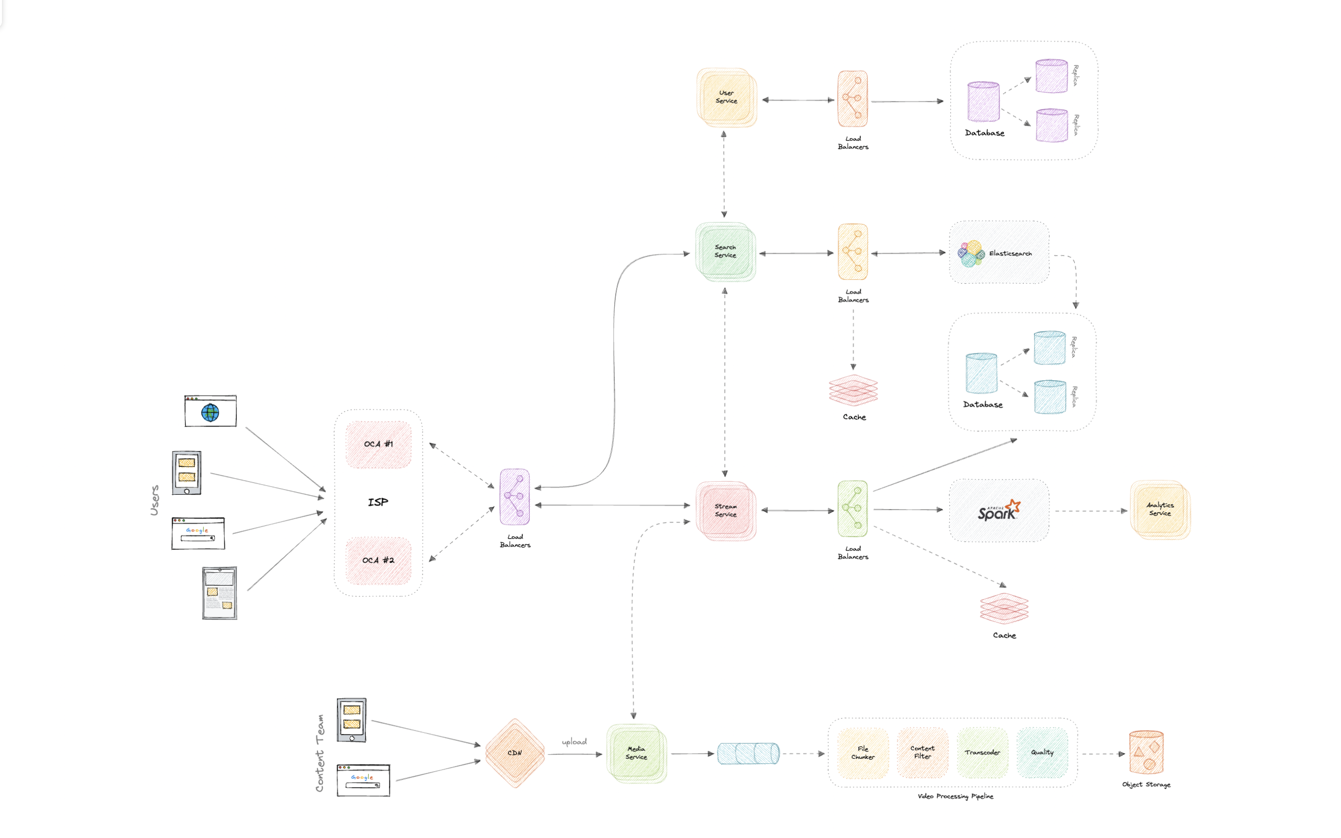
Let us identify and resolve bottlenecks such as single points of failure in our design:
- “What if one of our services crashes?”
- “How will we distribute our traffic between our components?”
- “How can we reduce the load on our database?”
- “How to improve the availability of our cache?”
To make our system more resilient we can do the following:
- Running multiple instances of each of our services.
- Introducing load balancers between clients, servers, databases, and cache servers.
- Using multiple read replicas for our databases.
- Multiple instances and replicas for our distributed cache.
Uber
Let’s design an Uber like ride-hailing service, similar to services like Lyft, OLA Cabs, etc.
What is Uber?
Uber is a mobility service provider, allowing users to book rides and a driver to transport them in a way similar to a taxi. It is available on the web and mobile platforms such as Android and iOS.
Requirements
Our system should meet the following requirements:
Functional requirements
We will design our system for two types of users: Customers and Drivers.
Customers
- Customers should be able to see all the cabs in the vicinity with an ETA and pricing information.
- Customers should be able to book a cab to a destination.
- Customers should be able to see the location of the driver.
Drivers
- Drivers should be able to accept or deny the customer requested ride.
- Once a driver accepts the ride, they should see the pickup location of the customer.
- Drivers should be able to mark the trip as complete on reaching the destination.
Non-Functional requirements
- High reliability.
- High availability with minimal latency.
- The system should be scalable and efficient.
Extended requirements
- Customers can rate the trip after it’s completed.
- Payment processing.
- Metrics and analytics.
Estimation and Constraints
Let’s start with the estimation and constraints.
Note: Make sure to check any scale or traffic-related assumptions with your interviewer.
Traffic
Let us assume we have 100 million daily active users (DAU) with 1 million drivers and on average our platform enables 10 million rides daily.
If on average each user performs 10 actions (such as request a check available rides, fares, book rides, etc.) we will have to handle 1 billion requests daily.
\[100 \space million \times 10 \space actions = 1 \space billion/day\]What would be Requests Per Second (RPS) for our system?
1 billion requests per day translate into 12K requests per second.
\[\frac{1 \space billion}{(24 \space hrs \times 3600 \space seconds)} = \sim 12K \space requests/second\]Storage
If we assume each message on average is 400 bytes, we will require about 400 GB of database storage every day.
\[1 \space billion \times 400 \space bytes = \sim 400 \space GB/day\]And for 10 years, we will require about 1.4 PB of storage.
\[400 \space GB \times 10 \space years \times 365 \space days = \sim 1.4 \space PB\]Bandwidth
As our system is handling 400 GB of ingress every day, we will require a minimum bandwidth of around 4 MB per second.
\[\frac{400 \space GB}{(24 \space hrs \times 3600 \space seconds)} = \sim 5 \space MB/second\]High-level estimate
Here is our high-level estimate:
| Type | Estimate |
|---|---|
| Daily active users (DAU) | 100 million |
| Requests per second (RPS) | 12K/s |
| Storage (per day) | ~400 GB |
| Storage (10 years) | ~1.4 PB |
| Bandwidth | ~5 MB/s |
Data model design
This is the general data model which reflects our requirements.
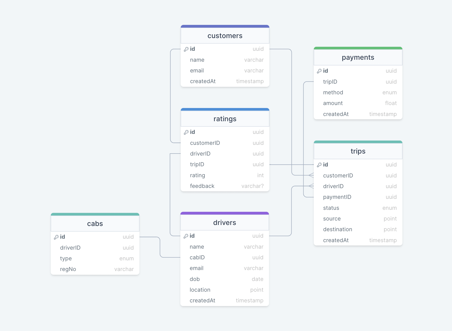
We have the following tables:
customers
This table will contain a customer’s information such as name, email, and other details.
drivers
This table will contain a driver’s information such as name, email, dob and other details.
trips
This table represents the trip taken by the customer and stores data such as source, destination, and status of the trip.
cabs
This table stores data such as the registration number, and type (like Uber Go, Uber XL, etc.) of the cab that the driver will be driving.
ratings
As the name suggests, this table stores the rating and feedback for the trip.
payments
The payments table contains the payment-related data with the corresponding tripID.
What kind of database should we use?
While our data model seems quite relational, we don’t necessarily need to store everything in a single database, as this can limit our scalability and quickly become a bottleneck.
We will split the data between different services each having ownership over a particular table. Then we can use a relational database such as PostgreSQL or a distributed NoSQL database such as Apache Cassandra for our use case.
API design
Let us do a basic API design for our services:
Request a Ride
Through this API, customers will be able to request a ride.
requestRide(customerID: UUID, source: Tuple<float>, destination: Tuple<float>, cabType: Enum<string>, paymentMethod: Enum<string>): Ride
Parameters
Customer ID (UUID): ID of the customer.
Source (Tuple<float>): Tuple containing the latitude and longitude of the trip’s starting location.
Destination (Tuple<float>): Tuple containing the latitude and longitude of the trip’s destination.
Returns
Result (boolean): Represents whether the operation was successful or not.
Cancel the Ride
This API will allow customers to cancel the ride.
cancelRide(customerID: UUID, reason?: string): boolean
Parameters
Customer ID (UUID): ID of the customer.
Reason (UUID): Reason for canceling the ride (optional).
Returns
Result (boolean): Represents whether the operation was successful or not.
Accept or Deny the Ride
This API will allow the driver to accept or deny the trip.
acceptRide(driverID: UUID, rideID: UUID): boolean
denyRide(driverID: UUID, rideID: UUID): boolean
Parameters
Driver ID (UUID): ID of the driver.
Ride ID (UUID): ID of the customer requested ride.
Returns
Result (boolean): Represents whether the operation was successful or not.
Start or End the Trip
Using this API, a driver will be able to start and end the trip.
startTrip(driverID: UUID, tripID: UUID): boolean
endTrip(driverID: UUID, tripID: UUID): boolean
Parameters
Driver ID (UUID): ID of the driver.
Trip ID (UUID): ID of the requested trip.
Returns
Result (boolean): Represents whether the operation was successful or not.
Rate the Trip
This API will enable customers to rate the trip.
rateTrip(customerID: UUID, tripID: UUID, rating: int, feedback?: string): boolean
Parameters
Customer ID (UUID): ID of the customer.
Trip ID (UUID): ID of the completed trip.
Rating (int): Rating of the trip.
Feedback (string): Feedback about the trip by the customer (optional).
Returns
Result (boolean): Represents whether the operation was successful or not.
High-level design
Now let us do a high-level design of our system.
Architecture
We will be using microservices architecture since it will make it easier to horizontally scale and decouple our services. Each service will have ownership of its own data model. Let’s try to divide our system into some core services.
Customer Service
This service handles customer-related concerns such as authentication and customer information.
Driver Service
This service handles driver-related concerns such as authentication and driver information.
Ride Service
This service will be responsible for ride matching and quadtree aggregation. It will be discussed in detail separately.
Trip Service
This service handles trip-related functionality in our system.
Payment Service
This service will be responsible for handling payments in our system.
Notification Service
This service will simply send push notifications to the users. It will be discussed in detail separately.
Analytics Service
This service will be used for metrics and analytics use cases.
What about inter-service communication and service discovery?
Since our architecture is microservices-based, services will be communicating with each other as well. Generally, REST or HTTP performs well but we can further improve the performance using gRPC which is more lightweight and efficient.
Service discovery is another thing we will have to take into account. We can also use a service mesh that enables managed, observable, and secure communication between individual services.
Note: Learn more about REST, GraphQL, gRPC and how they compare with each other.
How is the service expected to work?
Here’s how our service is expected to work:
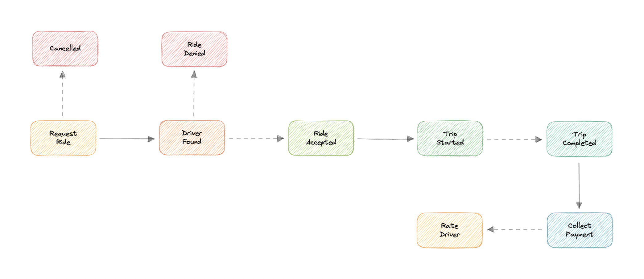
- Customer requests a ride by specifying the source, destination, cab type, payment method, etc.
- Ride service registers this request, finds nearby drivers, and calculates the estimated time of arrival (ETA).
- The request is then broadcasted to the nearby drivers for them to accept or deny.
- If the driver accepts, the customer is notified about the live location of the driver with the estimated time of arrival (ETA) while they wait for pickup.
- The customer is picked up and the driver can start the trip.
- Once the destination is reached, the driver will mark the ride as complete and collect payment.
- After the payment is complete, the customer can leave a rating and feedback for the trip if they like.
Location Tracking
How do we efficiently send and receive live location data from the client (customers and drivers) to our backend? We have two different options:
Pull model
The client can periodically send an HTTP request to servers to report its current location and receive ETA and pricing information. This can be achieved via something like Long polling.
Push model
The client opens a long-lived connection with the server and once new data is available it will be pushed to the client. We can use WebSockets or Server-Sent Events (SSE) for this.
The pull model approach is not scalable as it will create unnecessary request overhead on our servers and most of the time the response will be empty, thus wasting our resources. To minimize latency, using the push model with WebSockets is a better choice because then we can push data to the client once it’s available without any delay given the connection is open with the client. Also, WebSockets provide full-duplex communication, unlike Server-Sent Events (SSE) which are only unidirectional.
Additionally, the client application should have some sort of background job mechanism to ping GPS location while the application is in the background.
Note: Learn more about Long polling, WebSockets, Server-Sent Events (SSE).
Ride Matching
We need a way to efficiently store and query nearby drivers. Let’s explore different solutions we can incorporate into our design.
SQL
We already have access to the latitude and longitude of our customers, and with databases like PostgreSQL and MySQL we can perform a query to find nearby driver locations given a latitude and longitude (X, Y) within a radius (R).
SELECT * FROM locations WHERE lat BETWEEN X-R AND X+R AND long BETWEEN Y-R AND Y+R
However, this is not scalable, and performing this query on large datasets will be quite slow.
Geohashing
Geohashing is a geocoding method used to encode geographic coordinates such as latitude and longitude into short alphanumeric strings. It was created by Gustavo Niemeyer in 2008.
Geohash is a hierarchical spatial index that uses Base-32 alphabet encoding, the first character in a geohash identifies the initial location as one of the 32 cells. This cell will also contain 32 cells. This means that to represent a point, the world is recursively divided into smaller and smaller cells with each additional bit until the desired precision is attained. The precision factor also determines the size of the cell.

For example, San Francisco with coordinates 37.7564, -122.4016 can be represented in geohash as 9q8yy9mf.
Now, using the customer’s geohash we can determine the nearest available driver by simply comparing it with the driver’s geohash. For better performance, we will index and store the geohash of the driver in memory for faster retrieval.
Quadtrees
A Quadtree is a tree data structure in which each internal node has exactly four children. They are often used to partition a two-dimensional space by recursively subdividing it into four quadrants or regions. Each child or leaf node stores spatial information. Quadtrees are the two-dimensional analog of Octrees which are used to partition three-dimensional space.

Quadtrees enable us to search points within a two-dimensional range efficiently, where those points are defined as latitude/longitude coordinates or as cartesian (x, y) coordinates.
We can save further computation by only subdividing a node after a certain threshold.

Quadtree seems perfect for our use case, we can update the Quadtree every time we receive a new location update from the driver. To reduce the load on the quadtree servers we can use an in-memory datastore such as Redis to cache the latest updates. And with the application of mapping algorithms such as the Hilbert curve, we can perform efficient range queries to find nearby drivers for the customer.
What about race conditions?
Race conditions can easily occur when a large number of customers will be requesting rides simultaneously. To avoid this, we can wrap our ride matching logic in a Mutex to avoid any race conditions. Furthermore, every action should be transactional in nature.
For more details, refer to Transactions and Distributed Transactions.
How to find the best drivers nearby?
Once we have a list of nearby drivers from the Quadtree servers, we can perform some sort of ranking based on parameters like average ratings, relevance, past customer feedback, etc. This will allow us to broadcast notifications to the best available drivers first.
Dealing with high demand
In cases of high demand, we can use the concept of Surge Pricing. Surge pricing is a dynamic pricing method where prices are temporarily increased as a reaction to increased demand and mostly limited supply. This surge price can be added to the base price of the trip.
For more details, learn how surge pricing works with Uber.
Payments
Handling payments at scale is challenging, to simplify our system we can use a third-party payment processor like Stripe or PayPal. Once the payment is complete, the payment processor will redirect the user back to our application and we can set up a webhook to capture all the payment-related data.
Notifications
Push notifications will be an integral part of our platform. We can use a message queue or a message broker such as Apache Kafka with the notification service to dispatch requests to Firebase Cloud Messaging (FCM) or Apple Push Notification Service (APNS) which will handle the delivery of the push notifications to user devices.
For more details, refer to the WhatsApp system design where we discuss push notifications.
Detailed design
It’s time to discuss our design decisions in detail.
Data Partitioning
To scale out our databases we will need to partition our data. Horizontal partitioning (aka Sharding) can be a good first step. We can shard our database either based on existing partition schemes or regions. If we divide the locations into regions using let’s say zip codes, we can effectively store all the data in a given region on a fixed node. But this can still cause uneven data and load distribution, we can solve this using Consistent hashing.
For more details, refer to Sharding and Consistent Hashing.
Metrics and Analytics
Recording analytics and metrics is one of our extended requirements. We can capture the data from different services and run analytics on the data using Apache Spark which is an open-source unified analytics engine for large-scale data processing. Additionally, we can store critical metadata in the views table to increase data points within our data.
Caching
In a location services-based platform, caching is important. We have to be able to cache the recent locations of the customers and drivers for fast retrieval. We can use solutions like Redis or Memcached but what kind of cache eviction policy would best fit our needs?
Which cache eviction policy to use?
Least Recently Used (LRU) can be a good policy for our system. In this policy, we discard the least recently used key first.
How to handle cache miss?
Whenever there is a cache miss, our servers can hit the database directly and update the cache with the new entries.
For more details, refer to Caching.
Identify and resolve bottlenecks
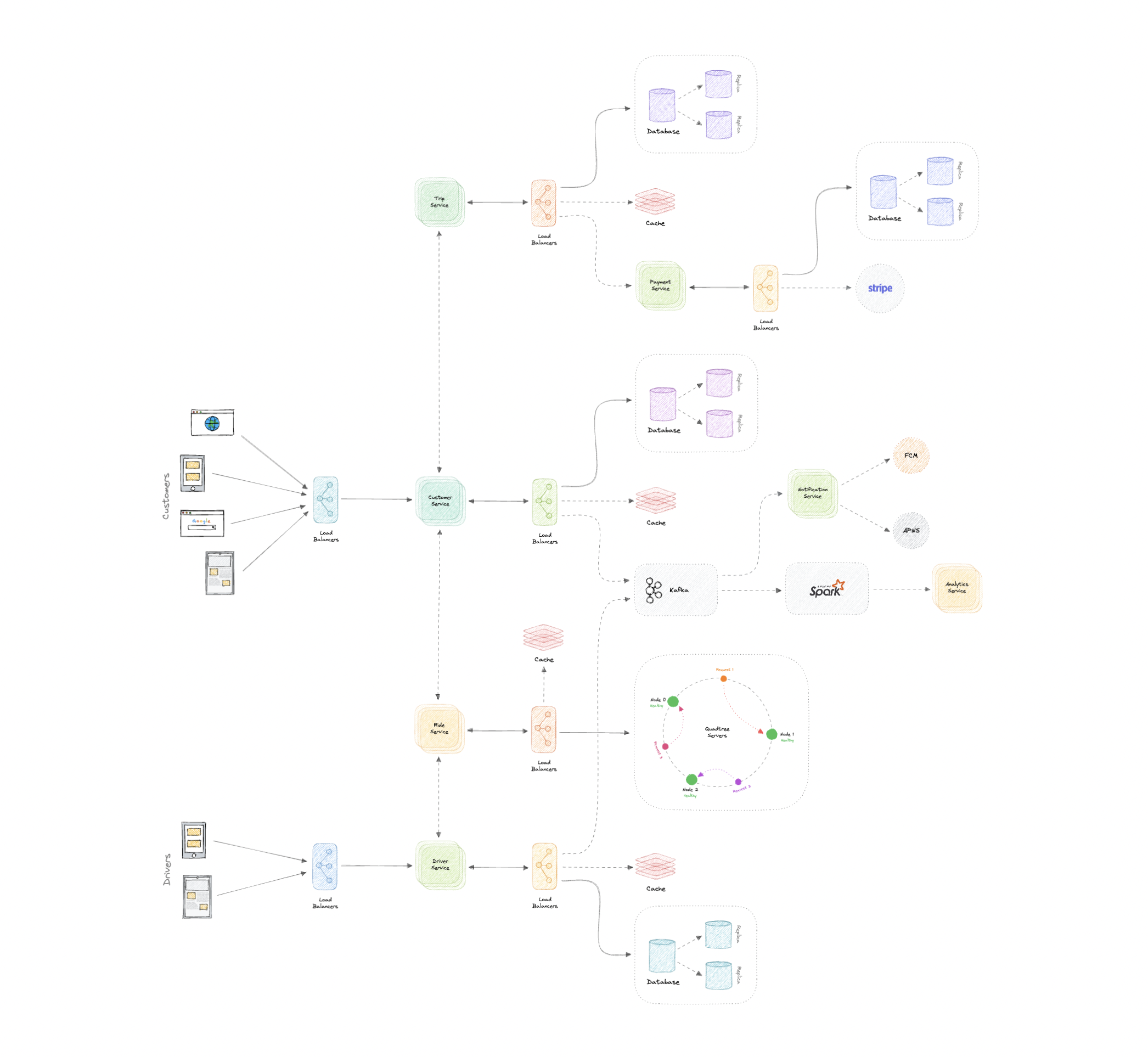
Let us identify and resolve bottlenecks such as single points of failure in our design:
- “What if one of our services crashes?”
- “How will we distribute our traffic between our components?”
- “How can we reduce the load on our database?”
- “How to improve the availability of our cache?”
- “How can we make our notification system more robust?”
To make our system more resilient we can do the following:
- Running multiple instances of each of our services.
- Introducing load balancers between clients, servers, databases, and cache servers.
- Using multiple read replicas for our databases.
- Multiple instances and replicas for our distributed cache.
- Exactly once delivery and message ordering is challenging in a distributed system, we can use a dedicated message broker such as Apache Kafka or NATS to make our notification system more robust.
Next Steps
Congratulations, you’ve finished the course!
Now that you know the fundamentals of System Design, here are some additional resources:
- Distributed Systems (by Dr. Martin Kleppmann)
- System Design Interview: An Insider’s Guide
- Microservices (by Chris Richardson)
- Serverless computing
- Kubernetes
It is also recommended to actively follow engineering blogs of companies putting what we learned in the course into practice at scale:
- Microsoft Engineering
- Google Research Blog
- Netflix Tech Blog
- AWS Blog
- Facebook Engineering
- Uber Engineering Blog
- Airbnb Engineering
- GitHub Engineering Blog
- Intel Software Blog
- LinkedIn Engineering
- Paypal Developer Blog
- Twitter Engineering
Last but not least, volunteer for new projects at your company, and learn from senior engineers and architects to further improve your system design skills.
I hope this course was a great learning experience. I would love to hear feedback from you.
Wishing you all the best for further learning!
References
Here are the resources that were referenced while creating this course.
- Cloudflare learning center
- IBM Blogs
- Fastly Blogs
- NS1 Blogs
- Grokking the System Design Interview
- System Design Primer
- AWS Blogs
- Martin Fowler
- PagerDuty resources
- VMWare Blogs
All the diagrams were made using Excalidraw and are available here.